H3CR-A
H3CR-A
19
H3CR-AP
The start input of the H3CR-AP is voltage input. (Voltage imposition or open)
Voltage Input Signal Levels
No-contact
input
Contact
input
1. Transistor ON
Residual voltage: 1 V max.
The voltage between terminals 6 and 7 must be 10.8 VDC min.
2. Transistor OFF
Leakage current: 0.01 mA max.
The voltage between terminals 6 and 7 must be 1.2 VDC max.
Use contacts that can adequately switch 0.1 mA at each oper-
ating voltage.
The voltage between terminals 6 and 7 with contacts ON or
OFF must satisfy the specified value.
Contacts ON
100-to-240-VAC and 100-to-125-VDC models: 85 to 264 VAC
or 85 to 137.5 VDC
24-to-48-VAC and 12-to-48-VDC models: 20.4 to 52.8 VAC or
10.8 to 52.8 VDC
Contacts OFF
100-to-240-VAC and 100-to-125-VDC models: 0 to 10 VAC or
0 to 10 VDC
24-to-48-VAC and 12-to-48-VDC models: 0 to 2.4 VAC or 0 to
1.2 VDC
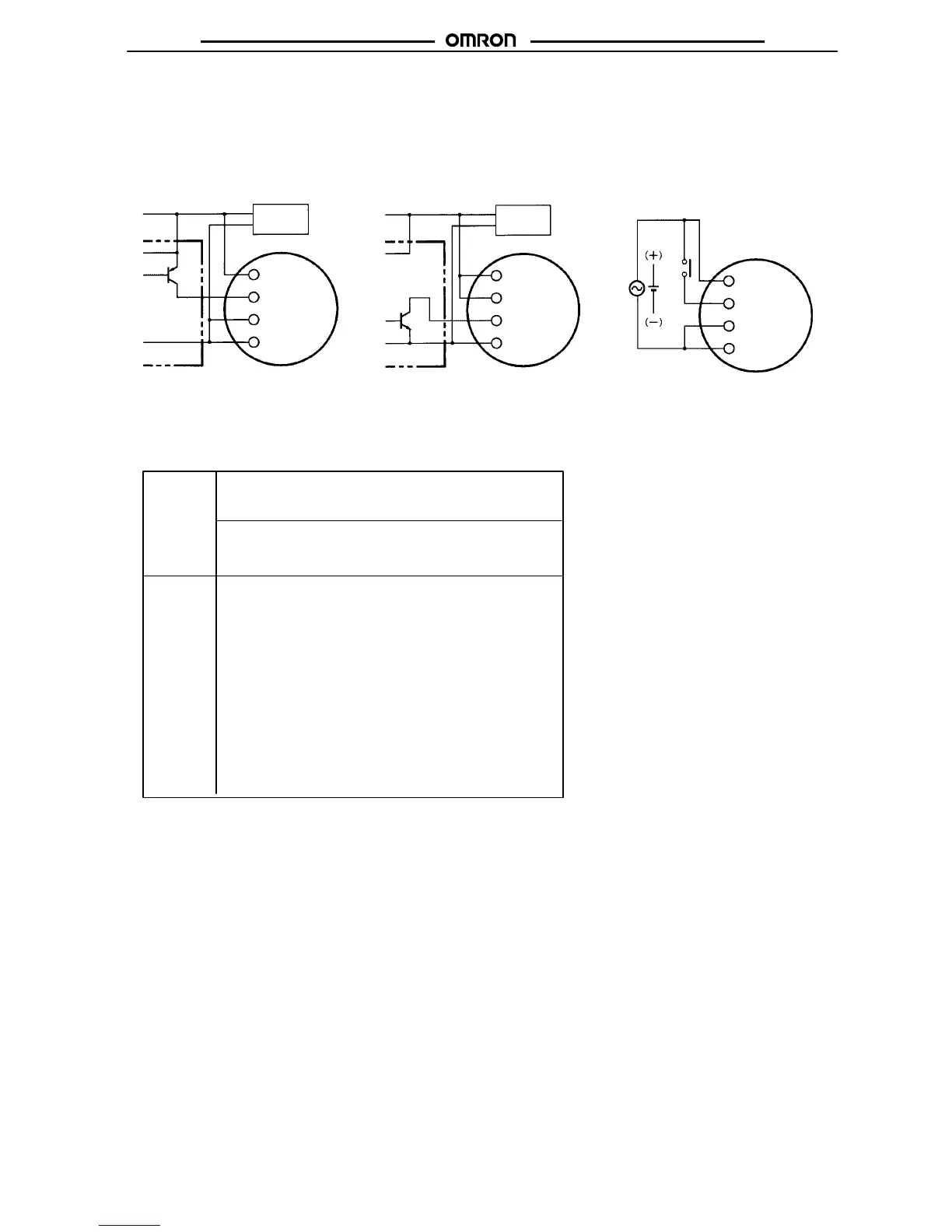
No-contact Input
(Connection to PNP open
collector output sensor)
No-contact Input
(Connection to NPN open
collector output sensor)
Contact Input
12 to 24 VDC
(sensor power supply)
Sensor
Timer
6 Start
Operates with PNP transistor ON
Operates with NPN transistor ON
12 to 24 VDC
(sensor power supply)
Timer
Sensor
Timer
Operates with relay ON
Note: Refer to the signal levels in the fol-
lowing table and be aware of the
minimum applicable load of the relay.
Voltage Inputs
10 Power
supply (+)
7 Input 0V
6 Start
10 Power
supply (+)
7 Input 0V
2 Power
supply
(–)
2 Power
supply
(–)
AC power supply
DC power supply
6 Start
10 Power
supply (+)
7 Input 0V
2 Power
supply
(–)
+
–
DC power
supply
+
–
DC power
supply
Note: The input circuit is isolated from the
power supply circuit. Thus, an NPN
transistor can be connected.

 Loading...


