H3DEH3DE
Timing Chart —
continued from previous page
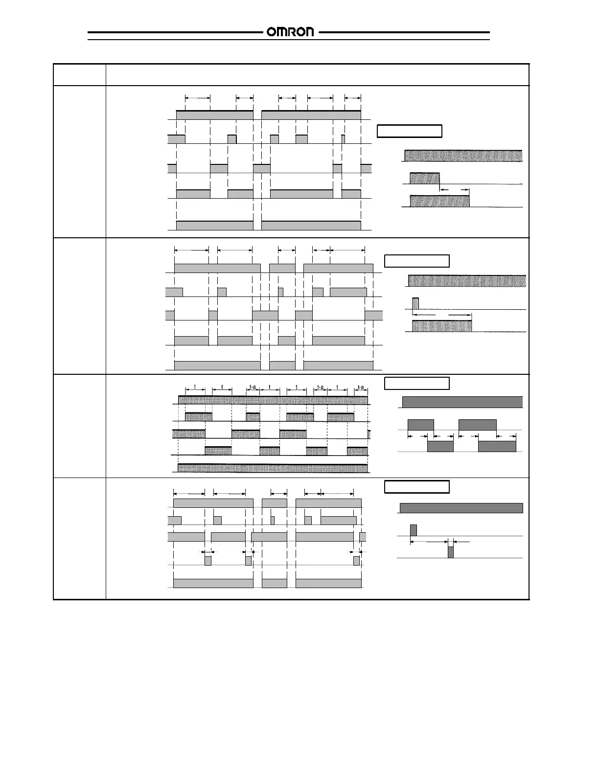
Operating
mode
Timing chart
D:
Signal
OFF-delay
Power (A
1
and A
2
)
Start (B
1
and A
2
)
(See Note.)
Power indicator
tt t -- a t -- a t t -- a
Basic operation
Power
Start
Output
t
* Start input is valid and re-triggerable while the
Timer is i n operation.
Output relay: NC
15 and 16
(25 and 26)
Output relay: NO
(output indicator)
15 and 18
(25 and 28)
*
E: Interval
Power
Start
Output
t
Basic operation
t--a
tt
Power (A
1
and A
2
)
Start (B
1
and A
2
)
(See Note.)
Power indicator
t
t--a
* For power-on operation, impose voltage to the
Start input. The Timer starts operating at the
moment the power is turned on.
** Start input is valid and re-triggerable while the
Timer is i n operation.
Output relay: NC
15 and 16
(25 and 26)
Output relay: NO
(output indicator)
15 and 18
(25 and 28)
*
**
G:
Signal
ON/OFF-
delay
Power (A
1
and A
2
)
Start (B
1
and A
2
)
(See Note.)
Power indicator
Power
Start
Output
Basic operation
* Start input is valid and re-triggerable while the
Timer is i n operation.
t t t t
Output relay: NC
15 and 16
(25 and 26)
Output relay: NO
(output indicator)
15 and 18
(25 and 28)
*
J:
One-shot
output
(ON delay)
Power (A
1
and A
2
)
Start (B
1
and A
2
)
(See Note.)
Power indicator
Power
Start
Output
Basic operation
* For power-on operation, impose voltage to the
Start input. The Timer starts operating at the
moment the power is turned on.
** Start input is valid and re-triggerable while the
Timer is i n operation.
tt tt--a t--a
Approx.
1±0.6 s
(fixed)
Approx.
1±0.6 s
(fixed)
Approx.
1±0.6 s
(fixed)
t Approx. 1±0.6 s
(fixed)
Output relay: NC
15 and 16
(25 and 26)
Output relay: NO
(output indicator)
15 and 18
(25 and 28)
*
**
Note: The start input of the H3DE-M1 or H3DE-M2 model is activated by applying a voltage to B1 and A2 terminals.
The voltage can be applied by turning on the contact between B1 and A1 (Refer to Terminal Arrangement).