EasyManua.ls Logo

Omron H3DE-S1 - User Manual

Omron H3DE-S1
14 pages
Print Icon
To Next Page IconTo Next Page
Loading...
Multifunction Timer H3DE
Analog Set Multifunction Timers
In Slim 22.5 mm Design
For Track Mounting
H
Wide AC/DC power supply range
(24 to 230 VAC/DC) minimizes inventory
H
12 VDC available in H3DE-M model
H
Programmable contacts (available in
-M2 and -S2 m odels) can enable and
disable a self -holding relay circuit
H
Eight operating modes in the H3DE-M
(four in the H3DE-S) offer wide
application flexibility
H
Time setting range 0.10 sec to 120 hrs
H
Finger protection terminal block
Ordering Information
J TIMER
Description Part number
Contact output Supply voltage Multifunctional Standard
DPDT (time-limit output SPDT);
and switchable SPDT
(
t
i
m
e
-
l
i
m
i
t
i
n
s
t
a
n
t
a
n
e
o
u
s
)
12 VDC H3DE-M2 DC12
(
t
i
me-
l
i
m
i
t
←→
i
ns
t
an
t
aneous
)
24 to 230
VAC/DC
H3DE-M2 AC/DC24-230 H3DE-S2 AC/DC24-230
SPDT (time-limit output SPDT) H3DE-M1 AC/DC24-230 H3DE-S1 AC/DC24-230
J MODEL NUMBER LEGEND
H3DE-j-j-j
123
1. M: Multifunction type
S: Standard type
2. 1: SPDT
2: DPDT
3. Supply voltage
J ACCESSORIES (ORDER SEPARATELY)
Item Description Part number
Mounting track 50 cm (l) x 7.3 mm (t) PFP-50N
1m(l)x7.3mm(t) PFP-100N
1 m (l) x 16 mm (t) PFP-100N2
End plate PFP-M
Spacer PFP-S
Question and Answer IconNeed help?

Do you have a question about the Omron H3DE-S1 and is the answer not in the manual?

Summary

H3 DE Specifications

General Specifications

Covers operating modes, terminal block, screw torque, input/output types, mounting, and approvals.

Time Range Settings

Details the available time scale displays and units for setting time on the timer.

Electrical Ratings

Specifies rated supply voltage, operating range, power reset, consumption, and control output capabilities.

H3 DE Operation Principles

Internal Block Diagram

Illustrates the functional blocks and signal flow within the H3DE-M and H3DE-S timer models.

Input;Output Functions

Explains the timer's input signal handling and control output behavior for different modes.

H3 DE Basic Operation Guide

Operational Timing Charts

Provides visual timing charts for various operating modes, showing signal sequences.

H3 DE Dimensions and Wiring

Terminal Arrangement Diagram

Displays the terminal layout and wiring connections for all H3DE timer models.

H3 DE Input Signal Requirements

Voltage Input Signal Levels

Defines the specific voltage levels required for 'ON' and 'OFF' states in transistor and contact inputs.

Overview

OMRON H3DE Multifunction Timer

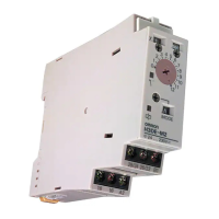
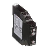
The OMRON H3DE is a series of analog set multifunction timers designed in a slim 22.5 mm form factor for track mounting. These timers offer a wide range of functionalities and are suitable for diverse industrial applications.

Function Description

The H3DE series provides precise timing control with various operating modes. The H3DE-M models offer eight operating modes, while the H3DE-S models provide four, ensuring broad application flexibility. Key features include:

  • Wide AC/DC Power Supply Range: A broad supply voltage range of 24 to 230 VAC/DC minimizes inventory requirements. A 12 VDC option is also available for the H3DE-M model (H3DE-M2 DC12).
  • Programmable Contacts: Available in -M2 and -S2 models, these contacts can be programmed to enable or disable a self-holding relay circuit, adding versatility to control schemes.
  • Time Setting Range: The timers offer a wide time setting range from 0.10 seconds to 120 hours, accommodating both short and long timing requirements.
  • Finger Protection Terminal Block: Designed with safety in mind, the terminal block provides finger protection during wiring and operation.

Important Technical Specifications

General:

  • Terminal Block: Clamps two 2.5 mm² max. bare terminals without sleeves.
  • Terminal Screw Tightening Torque: 0.98 N·m max. (approx. 10 kgf·cm max.).
  • Input Type: Voltage input.
  • Output Type: Relay (DPDT for -M2 and -S2 models; SPDT for -M1 and -S1 models).
  • Mounting Method: DIN track mounting (can be mounted to 35-mm DIN track with a plate thickness of 1 to 2.5 mm).
  • Approved Standards: UL508, CSA 22.2 No.14, EN61812-1, IEC60664-1 (VDE0110) 4 kV/2, VDE0106/P100.
  • Output Category (IEC60947-5-1): AC-13 (250 V 5A), AC-15 (250 V 3A), DC-13 (30 V 0.1A).

Operating Modes:

  • H3DE-M2/M1: ON-delay (Signal or Power), Repeat-cycle OFF start (Signal or Power), Repeat-cycle ON start (Signal or Power), Signal ON-/OFF-delay, Signal OFF-delay, Interval (Signal or Power), One-shot (Signal or Power).
  • H3DE-S2/S1: ON-delay, Repeat-cycle ON start, Interval, One-shot.

Time Ranges:

  • Time Scale Display (x 0.1): 0.1 to 1.2 seconds, 0.1 to 1.2 minutes, 0.1 to 1.2 hours, 1 to 12 hours.
  • Time Scale Display (x 1): 1 to 12 seconds, 1 to 12 minutes, 1 to 12 hours, 10 to 120 hours.
  • Note: When the main dial is set to "O" for all settings, the output operates instantaneously.

Ratings:

  • Rated Supply Voltage: 24 to 230 VAC/DC (50/60 Hz); 12 VDC (H3DE-M2 model only).
  • Operating Voltage Range: 85% to 110% of rated supply voltage.
  • Minimum Power-off Time: 0.1 seconds.
  • Reset Voltage: 2.4 VAC/DC max.
  • Power Consumption:
    • H3DE-M1: AC approx. 4.3 VA (2.2 W) at 230 VAC; DC approx. 0.7 W at 24 VDC.
    • H3DE-M2: AC approx. 4.8 VA (2.4 W) at 230 VAC; DC approx. 1.0 W at 24 VDC.
    • H3DE-S1: AC approx. 2.7 VA (1.6 W) at 230 VAC; DC approx. 0.7 W at 24 VDC.
    • H3DE-S2: AC approx. 3.2 VA (1.9 W) at 230 VAC; DC approx. 1.0 W at 24 VDC.
  • Voltage Input: Max. permissible capacitance between input lines (terminals B1 and A2): 2000 pF. Load connectable in parallel with inputs (terminals B1 and A2). H-level: 20.4 to 253 VAC/DC. L-level: 0 to 2.4 VAC/DC.
  • Control Output: Contact output: 5 A at 250 VAC with resistive load (cosφ = 1); 5 A at 30 VDC with resistive load (cosφ = 1).
  • Ambient Temperature: Operating: -10°C to 55°C (14 to 131°F) with no icing. Storage: -25°C to 65°C (-13°F to 149°F) with no icing.
  • Ambient Humidity: Operating: 35% to 85%.
  • DC Ripple Rate: 20% max.
  • Inrush Current (24 VDC): 0.25 A.

Characteristics:

  • Accuracy of Operating Time: ±1% max. of FS (±1% ±10 ms max. at 1.2-s range).
  • Setting Error: ±10% ±50 ms max. of FS.
  • Signal Input Time: 50 ms min.
  • Voltage Influence: ±0.5% max. of FS (±0.5% ±10 ms max. at 1.2-s range).
  • Temperature Influence: ±2% max. of FS (±2% ±10 ms max. at 1.2-s range).
  • Insulation Resistance: 100 MΩ min. at 500 VDC.
  • Dielectric Strength:
    • Between current-carrying metal parts and exposed non-current-carrying metal parts: 2,000 VAC for 1 min.
    • Between control output terminals and operating circuit: 2,000 VAC for 1 min.
    • Between contacts of different polarities: 2,000 VAC for 1 min.
    • Between contacts not located next to each other: 1,000 VAC for 1 min.
  • Vibration Resistance: Malfunction: 0.5-mm single amplitude at 10 to 55 Hz. Destruction: 0.75-mm single amplitude at 10 to 55 Hz.
  • Shock Resistance: Malfunction: 100 m/s² (approximately 10G). Destruction: 1,000 m/s² (approximately 100G).
  • Contact Material: AgNi+gold plating (uses G6RN-1 at 12 VDC).
  • Impulse Withstand Voltage: 3 kV (between power terminals); 4.5 kV (between current-carrying metal parts and exposed non-current-carrying metal parts).
  • Noise Immunity: Square-wave noise generated by noise simulator (pulse width: 100 ns/1 µs, 1-ns rise) ±1.5 kV.
  • Static Immunity: Malfunction: 4 kV. Destruction: 8 kV.
  • Life Expectancy: Mechanical: 10 million operations min. (under no load at 1,800 operations/h). Electrical: 100,000 operations min. (5 A at 250 VAC, resistive load at 360 operations/h).
  • EMC:
    • EMI: Emission Enclosure: EN55011 Group 1 class A. Emission AC Mains: EN55011 Group 1 class A. Harmonic Current: EN61000-3-2. Voltage Fluctuation and Flickering: EN61000-3-3.
    • EMS: Immunity ESD: EN61000-4-2: 6 kV contact discharge (level 3); 8 kV air discharge (level 3). Immunity RF-interference from AM Radio Waves: EN61000-4-3: 10 V/m (80 MHz to 1 GHz) (level 3). Immunity Burst: EN61000-4-4: 2 kV power port and output port (level 3); 1 kV control port with capacitive clamp (level 3). Immunity Surge: EN61000-4-5: 2 kV common mode (level 3); 1 kV differential mode (level 3).
  • Enclosure Rating: IP30 (Terminal block: IP20).
  • Weight: 120 g.

Usage Features

Selector Setting: The H3DE timers feature selectors for time unit, time scale, and operating mode. These selectors can be turned clockwise or counterclockwise and have a snap mechanism to secure them in position. It is crucial to ensure selectors are firmly secured to prevent malfunction.

Time Unit and Time Scale Selection: The desired time unit (sec, min, hrs, or 10h) is displayed in the time unit display window. The time scale (0.1 or 1) is selected via a dedicated selector and appears in the scale range display window.

Operating Mode Selection: Operating modes (A to J for H3DE-M, A, B2, E, or J for H3DE-S) are selected using a screwdriver, and the chosen mode is displayed in the operating mode display window.

Input Connections: The H3DE-M1/-M2 models support voltage inputs (voltage imposition or open). This includes connections to PNP output sensors, NPN output sensors, and contact inputs (e.g., relays). It is important to note that the input circuit and power supply circuit are configured independently. When connecting external signal input devices like relays or transistors, care must be taken to prevent short-circuiting due to sneak currents in the transformerless power supply system. Input terminals of multiple timers must be wired correctly to avoid phase differences or short circuits.

Output Type Selector Switch: H3DE-M2 and -S2 models include an output type selector switch on the bottom of the timer. This switch allows selection between time-limit output (default setting, using terminal numbers 25, 26, and 28) and instantaneous output (using terminal numbers 21, 22, and 24). When set to instantaneous, the relay R2 contacts turn ON/OFF synchronously with power supply changes.

Mounting: The H3DE should be mounted horizontally. For track mounting, hook portion (A) of the timer to an edge of the track, then depress the timer in direction (B). For removal, pull out portion (C) with a flat-blade screwdriver. A minimum clearance of 30 mm (1.18 in) between the H3DE and other equipment is recommended for ease of mounting and removal.

Power Supply: The H3DE Series uses a transformerless power supply system. Both AC and DC power supplies can be connected to the power input terminals without polarity considerations, except for the H3DE-M2 DC12 model, which requires designated polarity. DC power supplies must have a ripple factor of 20% or less and a mean voltage within the rated operating range. It is crucial to connect the power supply voltage through a relay or switch to ensure the voltage reaches a fixed value at once, preventing timer reset or errors. For input device power supply, an isolating transformer with mutually isolated and ungrounded primary and secondary windings is recommended.

Maintenance Features

Mounting Clearance: To ensure the longevity of internal components, especially when the load current is continuously supplied for extended periods, it is essential to provide adequate mounting clearance. The manual specifies mounting clearances (e.g., 50 mm min., 10 mm, 5 mm, 0 mm) and their impact on the maximum operating ambient temperature when mounting two or more H3DE units side-by-side. For example, with 0 mm clearance, the maximum operating ambient temperature is significantly reduced compared to 50 mm clearance.

Environment:

  • Noise Immunity: In environments with excessive electronic noise, separate the timer, wiring, and noise-generating equipment. Shielding the input signal wiring can further prevent electronic interference.
  • Chemical Exposure: Avoid using organic solvents (e.g., paint thinner) or highly acidic/basic solutions, as they can damage the outer casing.
  • Dust and Corrosive Gas: Do not use the timer in places exposed to dust, corrosive gases, or direct sunlight.
  • Storage and Operation Temperature: Ensure ambient temperature and humidity are within rated values during storage and operation. If stored below -10°C, allow the timer to reach room temperature for at least three hours before use.

Input Wires: Input wires should be as short as possible. If the floating capacity of wires exceeds 2,000 pF (approx. 17 m for cables with 120 pF/m), operation may be affected. Shielded cables should be used with particular attention.

VDE Conformance: The H3DE conforms to VDE 0435/P2021 under specific conditions. The output section provides basic isolation; supplementary basic isolation on the load side is required for reinforced isolation. The H3DE itself is designed for Overvoltage category III and Pollution degree 2. It features reinforced isolation with clearance of 5.5 mm and creepage distance of 5.5 mm at 230 VAC for front and bottom parts, and basic isolation with clearance of 3 mm and creepage distance of 3 mm at 230 VAC for the output.

Relay Life Expectancy: The built-in relay (G6RN) has a life expectancy of 50,000 operations min. (8 A at 250 VAC, resistive load at 360 operations/h). For reference, a maximum current of 0.15 A can be switched at 125 VDC (cosφ=1), and 0.1 A if L/R is 7 ms, with an expected life of 100,000 operations. The minimum applicable load is 10 mA at 5 VDC.

Omron H3DE-S1 Specifications

General IconGeneral
TypeDigital Timer
Power SupplyAC/DC
OutputSPDT Relay
Output TypeRelay
Operating Voltage100-240V AC
MountingDIN Rail
Display TypeLED
Contact Rating5 A at 250 VAC
Operating Temperature-10 to 55°C
Storage Temperature-25 to 65°C
Operating ModeOn Delay, Off Delay

Related product manuals