4-23
4 Screen Creation
NB-series Programmable Terminals Startup Guide Manual(V109)
4-4 Screen Creation
4
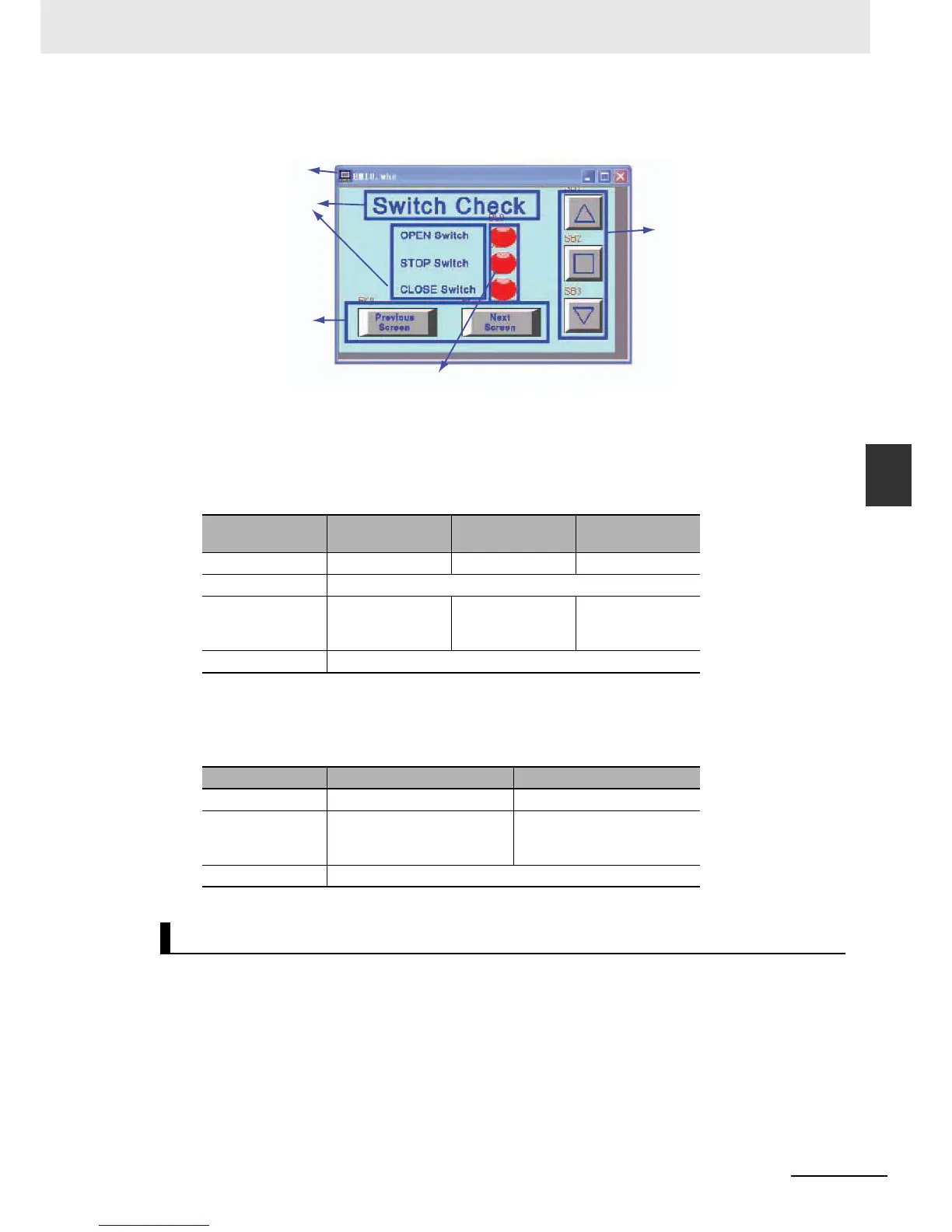
The whole screen is shown below. The creating methods for fixed text and Bit Button components for
[Open], [Stop] and [Close] garage door operations are the same as that of [1 Wait].
a Screen b Fixed Texts c Bit Lamp d Function Keys e Bit Button components
z Bit Lamp Components
The states of the [OPEN], [STOP] and [CLOSE] switches are shown by the lamp.
The property settings for Bit Lamp are:
z Function Key Components
These are used for switching to [6 Check 1] and [8 Check 3] screens.
The property settings for the Function Key components are:
The [8 Check 3] screen will be displayed when the screen-switching button on the
[7 Check 2] screen is pressed.
Configure functions below:
• Fixed text indicating the garage door state.
• Number Display components displaying the current values of TIM0 and CNT0 used in the ladder
program.
• Function Key components, buttons for switching to [7 Check 2] and [1 Wait] screens.
• Bit Button components, allocated to [Open], [Stop] and [Close] garage door operations respectively.
Corresponding
Name
OPEN Switch STOP Switch CLOSE Switch
Read Address W_bit 1.00 W_bit 1.01 W_bit 1.02
Function Normal
Label Transport font:
0: blank
1: OPEN
Transport font:
0: blank
1: STOP
Transport font:
0: blank
1: CLOSE
Graphics Use the vector graphic: Lamp2State1-00.vg
Screen Name Previous Screen Next Screen
Function Key Change Screen[6 Check 1] Change Screen[8 Check 3]
Label Transport font:
0: Previous Screen
1: Previous Screen
Transport font:
0: Next Screen
1: Next Screen
Graphics Use the vector graphic: CTRL_BAR001.vg
[8 Check 3]
a
b
d
e
c
 Loading...


