2-1 Components
Before explaining how to connect the RS-232C Interface Unit to the PT, the
names and functions of the RS-232C Interface Unit components are described.
Description of Components
The names and functions of the components of the RS-232C Interface Unit are
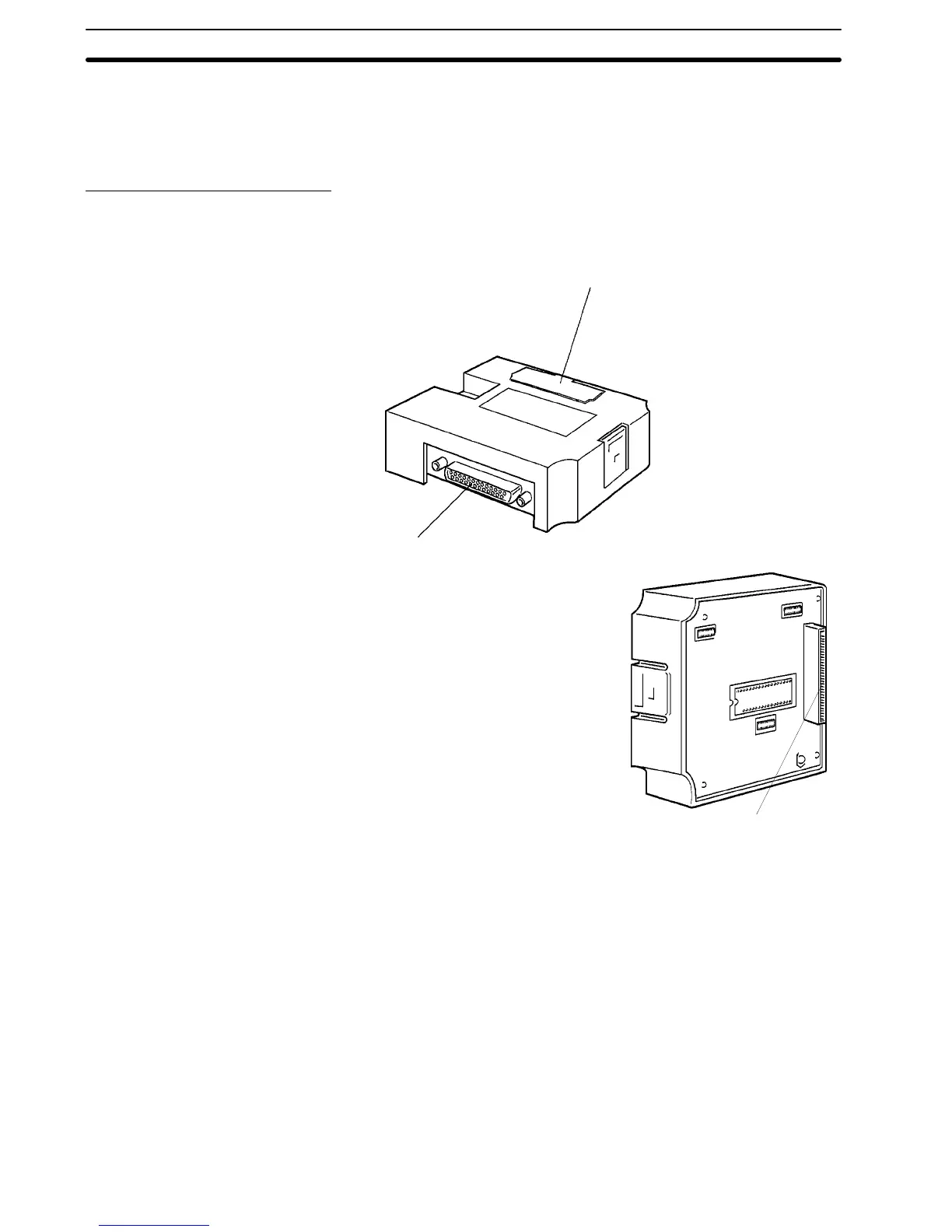
shown in the diagram below.
NT600M-LK201 RS-232C Interface Unit
Host Interface RS-232C Connector:
Connector for connection to the host computer.
RS-232C Interface Unit
front face
Switch cover:
Open this cover to reveal the DIP switches
(SW4) which set the basic operation of the
RS-232C Interface Unit.
RS-232C Interface Unit rear
face
Unit connector for
connection to the PT.
2-2 Installing the RS-232C Interface Unit
The methods of installing the RS-232C Interface Unit in the PT and setting the
DIP switches are described below.
2-2-1 Installation
Turnthe cut-out intheRS-232CInterface Unit to theleft andpushtheUnitinuntil
a “click” is heard.
In difficult-to-connect situations move the Unit when connecting the RS-232C
Interface Unit.
Note
Turn off the PT power supply when installing or removing the RS-232C/RS-422
Interface Unit.
Section 2-2