)
3-1 Components
Beforeexplaininghow toconnect theRS-422 Interface Unit to thePT, the names
and functions of the RS-422 Interface Unit Components are described.
Description of Components
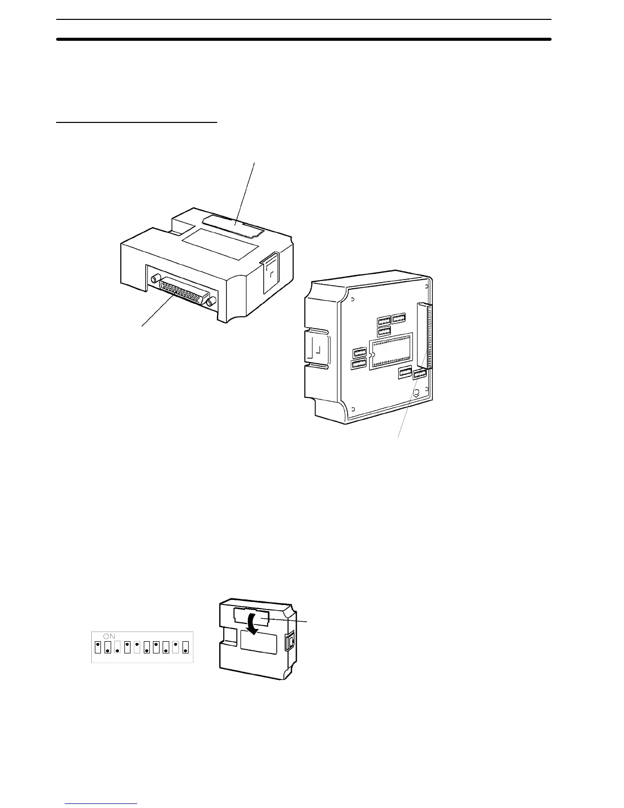
The names and functions of the components of the RS-422 Interface Unit are
shown in the diagram below.
Switch cover:
The DIP switch to set the basic operation (SW6) and the
rotary switches to set the terminal number (SW4, 5) are
under the switch cover on the front of the RS-422 Inter-
face Unit.
Host Interface RS-422 Connector:
Connector for connection to the host
computer.
PT Unit Connector:
Connector for connection to the PT.
RS-422 Front Face
RS-422 Rear Face
Installation of the RS-422 Interface Unit in the PT is identical to the RS-232C
Interface Unit. Refer to
Section 2 RS-232C Interface Unit Installation and Con-
nection
for details.
3-2 RS-422 Interface Unit Switch Settings
3-2-1 Switch Settings
Set the RS-422 Interface Unit rotary and DIP switches.
Switch cover
The DIP switches are under the switch
cover on the front of the Interface Unit.
1234567890
SW6-1 Data Bits
Data bits (see note below)
ON:8bits,OFF:7bits
SW6-2 Stop Bits
Stop bits (see note below)
ON: 1 bit, OFF: 2 bits
!
Section 3-2