(
SW6-3/4 Parity Check
None Even Odd
SW6-3: ON
SW6-4: ON
SW6-3: OFF
SW6-4: ON
SW6-3: OFF
SW6-4: OFF
SW6-5/6 XON/XOFF Control
ON OFF
SW6-5: OFF
SW6-6: OFF
SW6-5: ON
SW6-6: OFF
SW6-7/8/9 Baud Rate
Sets the PT Baud Rate
Set to the maximum baud rate supported by both the PT and the host computer.
However, the baud rate must be set to the same value on both devices.
19,200 bps 9,600 bps 4,800 bps 2,400 bps 1,200 bps 600 bps 300 bps
SW6-7: ON
SW6-8: ON
SW6-9: OFF
SW6-7: ON
SW6-8: OFF
SW6-9: ON
SW6-7: ON
SW6-8: OFF
SW6-9: OFF
SW6-7: OFF
SW6-8: ON
SW6-9: ON
SW6-7: OFF
SW6-8: ON
SW6-9: OFF
SW6-7: OFF
SW6-8: OFF
SW6-9: ON
SW6-7: OFF
SW6-8: OFF
SW6-9: OFF
Sets the internal 220
Ω
termination resistance.
ON: Terminal resistance ON
OFF: Terminal resistance OFF
Note
Set the data, stop , parity, and XON/XOFF, baud rate, and terminal resistance
bits to match one of the combinations as shown in the following.
7 data bits, Even parity, 2 stop bits 8databits,Noparity,2stopbits
7 data bits, Odd parity, 2 stop bits 8databits,Noparity,1stopbit
7 data bits, Even parity, 1 stop bit 8 data bits, Even parity, 1 stop bit
7 data bits, Odd parity, 1 stop bit 8 data bits, Odd parity, 1 stop bit
Caution
Turn off the power supply before setting the DIP switches.
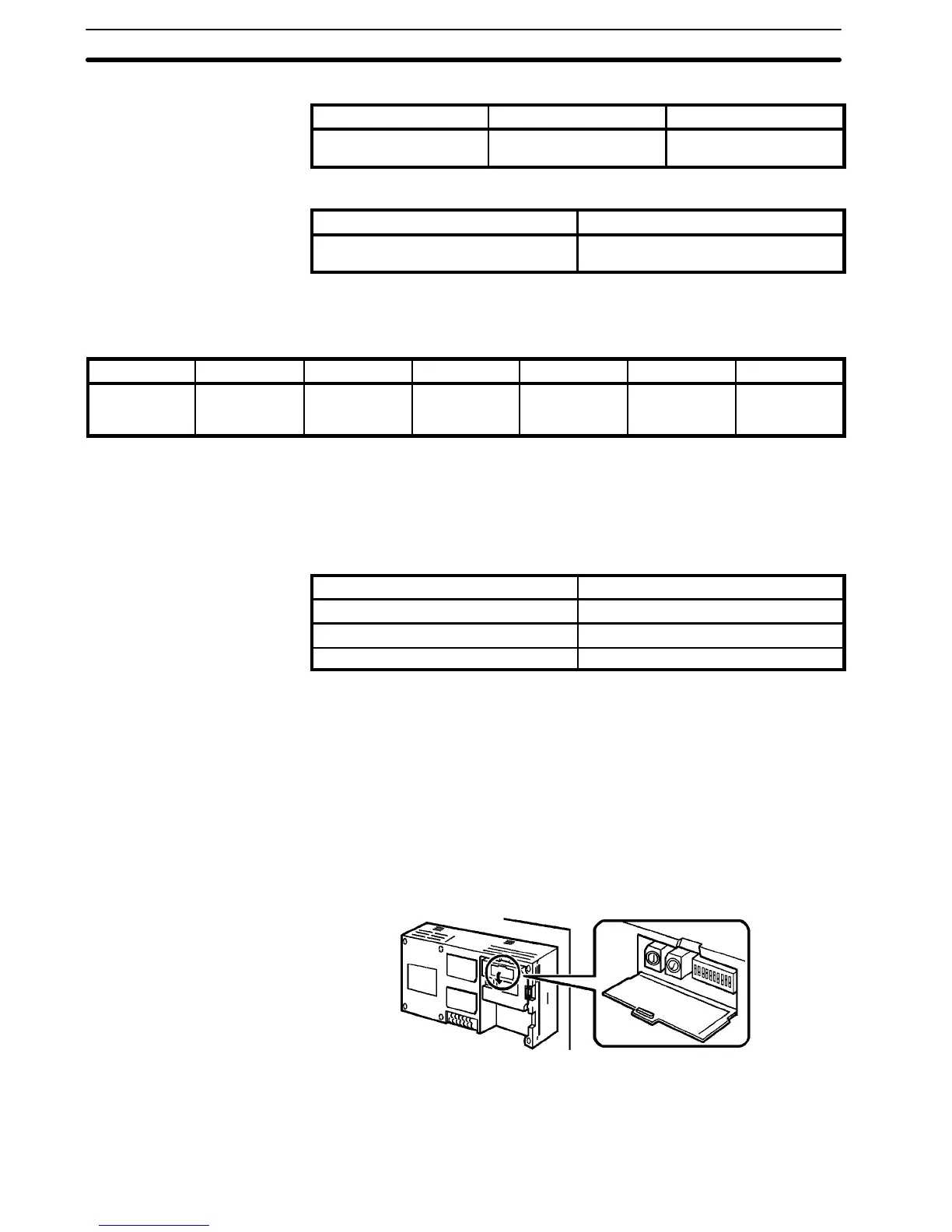
3-2-2 RS-422 Interface Unit Terminal Number
One host computer can be connected to a maximum of 16 PTs with RS-422
cables. A number, called a terminal number, is allocated to identify each PT.
The PT terminal number is set with the RS-422 Interface Unit rotary switches
(SW4, 5).
Set the terminal number as a decimal number between 0 and 15.
Turn the switch with a flathead screwdriver to the required number setting. Set
the tens digit on switch SW4 and the Units digit on switch SW5. The terminal
numbers are set independently of the order in which the PTs were connected.
The numbers do not have to begin from 0 and do not have to be consecutive.
SW6-10 Terminal
Resistance
!
Section 3-2