1
Examples
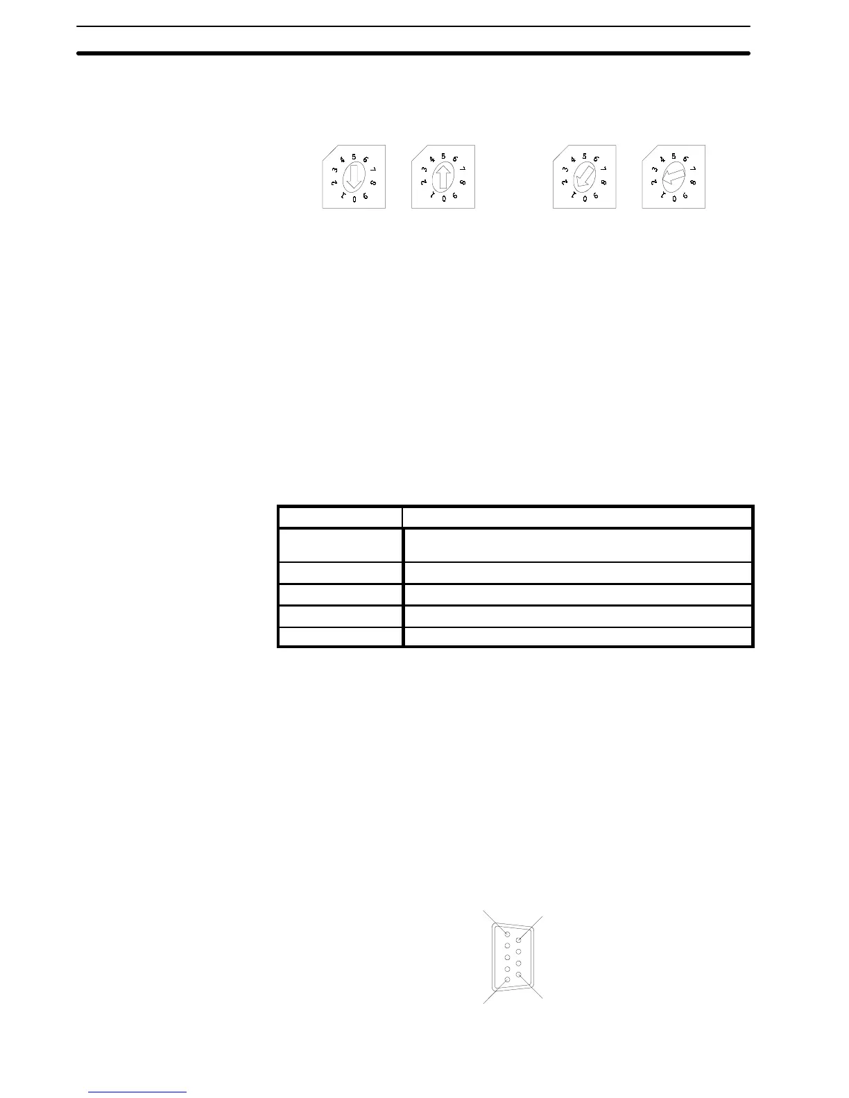
SW4 SW5
x10
1
x10
0
SW4 SW5
x10
1
x10
0
Set to 05 Set to 12
Thesettings of the PTDIP switches shouldbe identicalto thoseon the RS-232C
Interface Unit. Refer to
2-2-3 PT Unit DIP Switch Settings
.
3-3 Host Connections
Connect a PT with a RS-422 Interface Unit installed to the hostr with an RS-422
cable.
RS-422 connection allows a a maximum of 16 PTs to be connected to a single
host.
A computer or other control device with an RS-422 interface installed is a suit-
able host for connection to the PT.
3-3-1 Host Computer Communication Settings
Set the host communication conditions according to the following table.
Item Setting
Baud rate Set to the same baud rate as the PT: 300, 600, 1200, 2400,
4800, 9600, 19200
Data bits 7bits/8bits
Stop bits 1 bit/2 bits
Parity Even, Odd, None
XON/XOFF control ON/OFF
Note
Set the same communication conditions at the PT and host.
Refer to the appropriate instruction manuals for the method of setting the host
computer communication conditions.
Set to the maximum baud rate supported by both the PT and host computer.
3-3-2 Connector Pin Arrangement
The connection between the PT and host with an RS-422 cable is described be-
low.
The connector and cable specifications are described below.
Electrical characteristics: Conforms to EIA RS-422 specifications.
Signal direction: Signal input and output are relative to the host.
6
1
5
9
RS-422 Interface Unit
Section 3-3