Appendix C ' % &
#
Connector pin # Signal name Abbrevi-
Signal direction
ation
Input Output
1 Frame ground FG --- ---
2 Send data SD (TXD) Yes
3 Receive data RD (RXD) Yes
4 Request to send RS (RTS) Yes
5 Clear to send CS (CTS) Yes
6 DR --- ---
7 Signal ground SG (GND) --- ---
8 CD
20 Data terminal ready ER (DTR) Yes
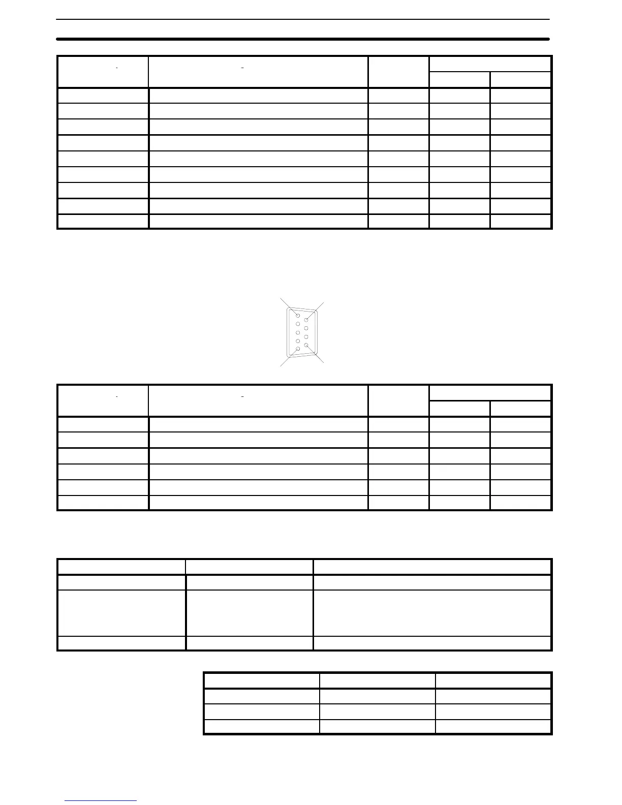
RS-422 Cable Connection
Connector: RS-422
Electrical characteristics: Complies with EIA RS-422
Signal direction: Signal input and output is relative to the PT or host.
6
1
5
9
Connector pin # Signal name Abbrevi-
Signal direction
ation
Input Output
1 Receive data B (+) RDB Yes
3 Signal ground SG --- ---
5 Send data B (+) SDB Yes
6 Receive data A (--) RDA Yes
7 Frame ground SG (GND) --- ---
9 Send data A (--) SDA Yes
Optical-fiber Cable Connections Maximum connection length is 500 m.
System configuration: 1-to-1 connection
The parts required for the connector cable are shown in the table below.
Name Model Remarks
RS-232C connector cable XZ7-10048 25-pin to 25-pin (2 m) manufactured by OMRON
Optical fiber cable 3 types of optical-fiber cable can be used:
APF (plastic optical-fiber cable)
PCF (plastic-clad optical-fiber cable)
H-PCF (hard plastic-clad quartz optical-fiber cable)
Link Adaptor B500-AL004(-P) 100/200 VAC, manufactured by OMRON
The transmission distance depends on the type of cable and the type of Link Adaptor.
Optical-fiber cable B500-AL004-P B500-AL004
APF 20 m No connection
H-PCF 100 m 200 m
PCF 200 m 800 m
Refer to the optical fiber and Link Adaptor manuals for information on the optical-fiber cable specifications.