3 - 7
3 Specifications
G5-series Linear Motors/Servo Drives With Built-in EtherCAT Communications
3-1 Servo Drive Specifications
3
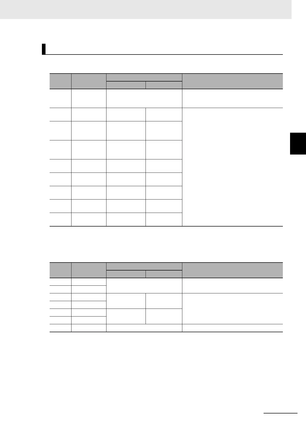
3-1-5 Control I/O Specifications (CN1)
z CN1 Control Inputs
*1 Refer to 7-1 Sequence I/O Signals on page 7-2 for the allocations.
z CN1 Control Outputs
*1 Refer to 7-1 Sequence I/O Signals on page 7-2 for the allocations.
Control I/O Signal Tables
Pin No. Symbol
Signal
Function and interface
Name Default
6 +24 VIN Power supply input 12 to 24 VDC The positive input terminal of the external
power supply (12 to 24 VDC) for sequence
inputs
5 IN1 General-purpose
Input 1
Immediate Stop
Input
These are general-purpose inputs. The input
functions can be selected with servo parameter
objects.
*1
External Latch Signals 1 to 3 can be allocated
only to IN5 to IN7 (or pins 10 to 12)
respectively.
7 IN2 General-purpose
Input 2
Positive Drive
Prohibition
Input
8 IN3 General-purpose
Input 3
Negative Drive
Prohibition
Input
9 IN4 General-purpose
Input 4
Origin
Proximity Input
10 IN5 General-purpose
Input 5
External Latch
Signal 3
11 IN6 General-purpose
Input 6
External Latch
Signal 2
12 IN7 General-purpose
Input 7
External Latch
Signal 1
13 IN8 General-purpose
Input 8
Monitor Input 0
Pin No. Symbol
Signal
Function and interface
Name Default
3 /ALM Error Output The output turns OFF when an error occurs in
the Servo Drive.
4ALMCOM
1 OUTM1 General-purpose
Output 1
Brake Interlock
Output
These are general-purpose outputs. The input
functions can be selected with servo parameter
objects.
*1
2 OUTM1COM
25 OUTM2 General-purpose
Output 2
Servo Ready
Output
26 OUTM2COM
16 GND Signal ground This is the signal ground.
 Loading...
