SYSMAC CP-series Expansion Units
I/O Wiring Diagram
© OMRON Corporation 2007 All Rights Reserved 0676428-7C
CP1W-AD041
Analog Input Unit (4 Points)
CP1W-DA041
Analog Output Unit (4 Points)
CP1W-DA021
Analog Output Unit (2 Points)
CP1W-MAD11
Analog Input (2 Points)/
Analog Output (1 Point)
I IN1 V IN2 COM2 I IN3 V IN4 COM4 AG
V IN1 COM1 I IN2 V IN3 COM3 I IN4 NC
Note 1
Wiring for other inputs is the same as that for input 1.
Note 2
When using current inputs, voltage input terminals
must be short-circuited with current input terminals.
Input Terminal Arrangement
V IN1
Voltage input 1
I IN1
Current input 1
COM1
Input common 1
V IN2
Voltage input 2
I IN2
Current input 2
COM2
Input common 2
V IN3
Voltage input 3
I IN3
Current input 3
COM3
Input common 3
V IN4
Voltage input 4
I IN4
Current input 4
COM4
Input common 4
nalog device
with current
output
nalog device
with voltage
output
+
+
-
-
I OUT1 V OUT2 COM2 I OUT3 V OUT4 COM4 NC
V OUT1 COM1 I OUT2 V OUT3 COM3 I OUT4 NC
+
Output Terminal Arrangement
Voltage output 1 V OUT1
Current output 1 I OUT1
Output common 1 COM1
Voltage output 2 V OUT2
Current output 2 I OUT2
Output common 2 COM2
Voltage output 3 V OUT3
Current output 3 I OUT3
Output common 3 COM3
Voltage output 4 V OUT4
Current output 4 I OUT4
Output common 4 COM4
Analog device
with current
input
Analog device
with voltage
input
+
-
-
Note
Wiring for other outputs is the same as that for output 1.
I OUT1 V OUT2 COM2 NC NC NC NC
V OUT1 COM1 I OUT2 NC NC NC NC
+
Output Terminal Arrangement
Voltage output 1
V OUT1
Current output 1
I OUT1
Output common 1
COM1
Voltage output 2
V OUT2
Current output 2
I OUT2
Output common 2
COM2
Analog device
with current
input
Analog device
with voltage
input
+
-
-
Note
Wiring for other outputs is the same as that for output 1.
nalog device
with voltage
input
+
-
I OUT V IN1 COM1 I IN2
V OUT COM I IN1 V IN2 COM2
+
Terminal Arrangement
nalog device
with current
input
-
nalog device
with current
output
nalog device
with voltage
output
+
+
-
-
V OUT
Voltage output
I OUT
Current output
COM
Output common
V IN1
Voltage input 1
I IN1
Current input 1
COM1
Input common 1
V IN2
Voltage input 2
I IN2
Current input 2
COM2
Input common 2
Note 1
Wiring for input 2 is the same as that for input 1.
Note 2
When using current inputs, voltage input terminals
must be short-circuited with current input terminals.
CP1W-TS001
Temperature Sensor Unit
Thermocouples (2 Points)
CP1W-TS002
Temperature Sensor Unit
Thermocouples (4 Points)
CP1W-TS101
Temperature Sensor Unit
Platinum resistance thermometer
(2 Points)
CP1W-TS102
Temperature Sensor Unit
Platinum resistance thermometer
(4 Points)
Loop 0 +
Loop 1 +
Cold junction
com
ensator
Cold junction
com
ensator
NC
NC
NC
Loop 0 -
Loop 1 -
NC
NC
NC
NC
NC
Input Terminal Arrangement
Loop 0 +
Loop 0 -
Temperature
input 0
Loop 1 +
Loop 1 -
Temperature
input 1
NC
Cold junction
compensator
NC
Cold junction
compensator
NC
NC
NC
NC
NC
+
+
-
-
Cold junction
compensator
Thermocouple K or J
Loop 0 +
Loop 1 +
Cold junction
compensator
Cold junction
compensator
Loop 2 +
Loop 3 +
NC
Loop 0 -
Loop 1 -
NC
NC
NC
Loop 2 -
Loop 3 -
Input Terminal Arrangement
Loop 0 +
Temperature
input 0
Loop 0 -
Loop 1 +
Temperature
input 1
Loop 1 -
NC
Cold junction
compensator
NC
Cold junction
compensator
NC
Loop 2 +
Temperature
input 2
Loop 2 -
Loop 3 +
Temperature
input 3
Loop 3 -
NC
+
+
+
+
-
Cold junction
compensator
Thermocouple K or J
Input 0A
Input 1A
Input 1B
NC
NC
NC
NC
Input 0B
Input 0B
Input 1B
NC
NC
NC
NC
Input Terminal Arrangement
Input 0A
Input 0B
Input 0B
Temperature
input 0
Input 1A
Input 1B
Input 1B
Temperature
input 1
NC
NC
NC
NC
NC
NC
NC
NC
Pt100 or JPt100 platinum resistance thermometers
Pt
Pt
Input 0A
Input 1A
Input 1B
NC
Input 2A
Input 3A
Input 3B
Input 0B
Input 0B
Input1B
NC
Input 2B
Input 2B
Input 3B
Input Terminal Arrangement
Input 0A
Temperature
input 0
Input 0B
Input 0B
Input 1A
Temperature
input 1
Input 1B
Input 1B
NC
NC
Input 2A
Temperature
input 2
Input 2B
Input 2B
Input 3A
Temperature
input 3
Input 3B
Input 3B
Pt100 or JPt100 platinum resistance thermometers
Pt
Pt
Pt
Pt
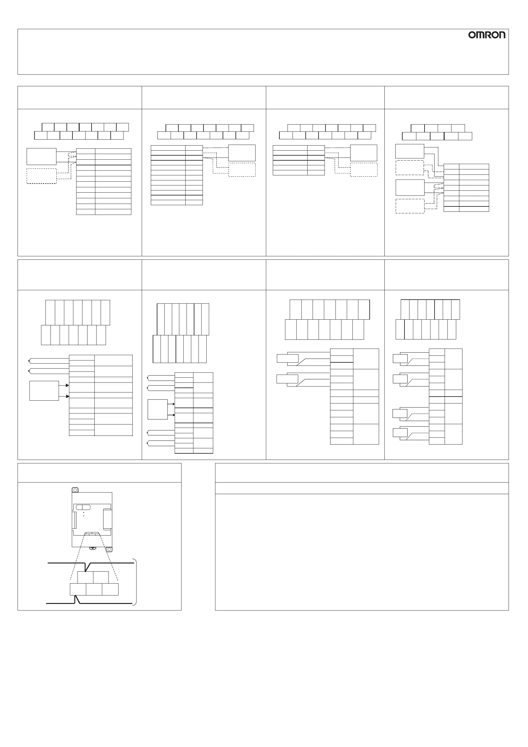
CP1W-SRT21
CompoBus/S I/O Link Unit
Precautions for Compliance with UL Standards and CSA Standards
BD H NC(BS+)
BD L NC(BS-) NC
Terminal Arrangement
Connect the
CompoBus/S
Communications
Cable.
BD L NC(BS- ) NC
BD H NC(BS+)
S
COMM
ERR
No.
SRT21
EXP
Notice to Users of the SYSMAC CP1 I/O Units in the USA and Canada
Please observe the following installation information instead of the general information in the instruction manuals in
order to use the product under the certified conditions of UL and CSA when the products are installed in the USA
and Canada. These conditions are according to the National Electrical Code in the USA and the Canadian Electrical
Code and may vary from information given in the product manuals or safety precautions.
I/O Wiring
Do not use crimp terminal for I/O wiring. Tighten the screw directly on the solid wire.
Do not insert more than one wire in one terminal.
Tightening torque: 4.4 Lb In. (0.5 N·m)
Wire range: AWG 26 to 18 (Solid wire only)
Surrounding Air Temperature
Rated temperature: 55
。
C
 Loading...


