Programmable Relay ZEN V2 Units 33
■ Memory Cassette and CPU Unit Combinations
Be aware of the following restrictions when using a Memory Cassette containing a program that was stored from a CPU Unit with a different version
of system software.
Note: 1. The display functions (display clear: -CD@ and day/month display: DAT1) cannot be used and will be ignored.
2. Only the memory area ranges supported by the pre-V1 CPU Units can be used for Timers, Holding Timers, Counters, Weekly Timers, Calendar Timers, and
Displays (i.e., only half of each).
3. Only 6 inputs and 4 outputs can be used in the CPU Unit I/O bits. Any others will be ignored.
4. Twin timer operation for timers, multiple-day operation and pulse operation for weekly timers, the 8-digit counter, and 8-digit comparators cannot be used.
New Zealand and Australia cannot be set for Daylight Saving Time (DST).
■ Support Software and CPU Unit Combinations
Note: 1. The display functions (display clear: -CD@ and day/month display: DAT1) cannot be used and will be ignored.
2. Only the memory area ranges supported by the pre-V1 CPU Units can be used for Timers, Holding Timers, Counters, Weekly Timers, Calendar Timers, and
Displays (i.e., only half of each).
3. Twin timer operation for timers, multiple-day operation and pulse operation for weekly timers, the 8-digit counter, and 8-digit comparators cannot be used.
New Zealand and Australia cannot be set for Daylight Saving Time (DST).
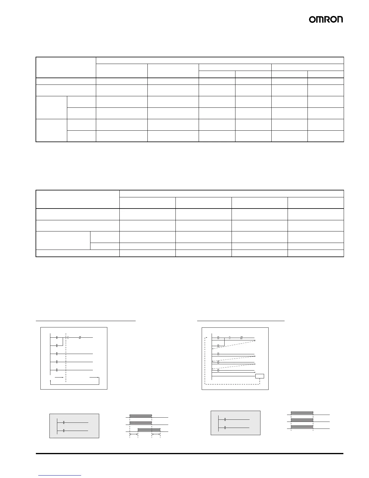
■ Difference between ZEN Programmable Relays and PLC Ladder
Program Execution
ZEN Programmable Relays
The ON/OFF status produced by an output contact will not be used
as the input contact status in the same cycle, but it can be used in
the next cycle.
OMRON SYSMAC PLCs
When the following instructions are executed, Q0 turns ON/OFF
at the same time as the other bits.
System software version
of CPU Unit used to write
the Memory Cassette
System software version of CPU Unit used to read the Memory Cassette
Ver. 1.0 Ver. 1.1 Ver. 2.0 (V1 CPU Units) Ver. 3.0 (V2 CPU Units)
10 I/O points 20 I/O points 10 I/O points 20 I/O points
Ver. 1.0OKOKOKOKOKOK
Ver. 1.1 Restrictions (See note
1.)
OK OK OK OK OK
Ver. 2 .0
(V1 CPU
Units)
10 I/O points Restrictions
(See notes 1 and 2.)
Restrictions
(See note 2.)
OK OK OK OK
20 I/O points Restrictions
(See notes 1, 2, and 3.)
Restrictions
(See notes 2 and 3.)
Restrictions
(See note 3.)
OK Restrictions
(See note 3.)
OK
Ver. 3 .0
(V2 CPU
Units)
10 I/O points Restrictions
(See notes 1, 2, and 4.)
Restrictions
(See notes 2 and 4.)
Restrictions
(See note 4.)
Restrictions
(See note 4.)
OK OK
20 I/O points Restrictions
(See notes 1 to 4.)
Restrictions
(See notes 2, 3, and 4.)
Restrictions
(See note 4.)
Restrictions
(See note 4.)
Restrictions
(See note 3.)
OK
CPU Unit system software Support Software
Ver. 1.0
ZEN-SOFT01
Ver. 2.0
ZEN-SOFT01-V2
Ver. 3.0
ZEN-SOFT01-V3
Ver. 4.1
ZEN-SOFT01-V4
Ver. 1.0 (Pre-V1 Units) OK OK Restrictions
(See notes 1 and 2.)
Restrictions
(See notes 1, 2, and 3.)
Ver. 1.1 (Pre-V1 Units) Restrictions
(See note 1.)
OK Restrictions
(See note 2.)
Restrictions
(See notes 2 and 3.)
Ver. 2.0 (V1 CPU Units) 10 I/O points Restrictions
(See notes 1 and 2.)
Restrictions
(See note 2.)
OK Restrictions
(See note 3.)
20 I/O points Not applicable. Not applicable. OK Restrictions (See note 3.)
Ver. 3.0 (V2 CPU Units) Not applicable. Not applicable. Not applicable. OK
0
1
2
3
4
I0
Bus bar
Executed sequentially
from the bus bar.
I1 I2
[ Q0
[ Q1
TT0
[ Q2
Q0
I3
I4
T0
ZEN executes the entire
ladder program (up to 96
lines) from the first to last line
at one time. Each row is
executed in order from left to
right starting from the left bus
bar.
1 cycle 1 cycle
0
1
I0
M0
Q0
I0
[ M0
[ Q0
M0
0
1
2
3
4
I0
END
I1 I2
[ Q0
[ Q1
TT0
[ Q2
Q0
I3
I4
T0
PLCs execute ladder
programs one rung (circuit) at
a time, starting with the top
rung and executing it in order
from the left. When the END
instruction is reached, the
program is executed again
from the first rung.
0
1
I0
M0
Q0
I0
[ M0
[ Q0
M0


 To Next Page
 Loading...