Do you have a question about the Omron G9SA-321-T075 and is the answer not in the manual?
Details on power supply voltage, operating range, and power consumption.
Technical characteristics including resistance, time, and durability.
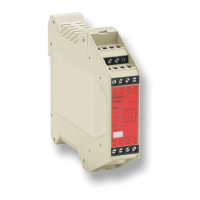
Dimensional drawings and terminal arrangements for main G9SA units.
Dimensional drawings and terminal arrangements for Expansion Units.
Wiring diagrams for internal connections of G9SA models.
Safety warnings, installation, wiring, and connector cover guidelines.
Guidelines for mounting multiple units, connecting inputs, and safety categories.
Procedures for ground shorts, input resetting, and OFF delay resetting.
List of standards certified by the G9SA series.
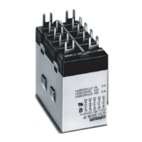
Precautions for mounting and handling Relays with forcibly guided contacts.
Principles of switching resistive, inductive loads, voltage, and current.
Typical examples and guidelines for contact protection circuits.
Factors affecting electrical durability and understanding failure rates.
Diagnosing and resolving faults related to operation and release.
Troubleshooting coil burning, contact welding, and contact failure.
Addressing abnormal contact consumption and humming issues.
Establishing risk assessment, safety policy, and understanding product roles.
Guidelines for installing products, adhering to laws, and observing usage precautions.
References to key international standards for safety and risk assessment.
| Type | Safety Relay |
|---|---|
| Number of Safety Contacts | 3 |
| Number of Auxiliary Contacts | 1 |
| Rated Voltage | 24 VDC |
| Rated Current | 5 A |
| Coil Voltage | 24 VDC |
| Electrical Life | 100, 000 operations |
| Mechanical Life | 10, 000, 000 operations |
| Shock Resistance | 1, 000 m/s² |
| Terminal Type | Screw terminals |
| Contact Rating | 5 A at 250 VAC, 5 A at 30 VDC |
| Operate Time | 15 ms |
| Release Time | 10 ms |
| Insulation Resistance | 100 MΩ min. at 500 VDC |
| Vibration Resistance | 10 to 55 Hz |
| Mounting Type | DIN Rail |
| Operating Temperature | -25°C to +55°C |
| Ambient Temperature | -25°C to +55°C |