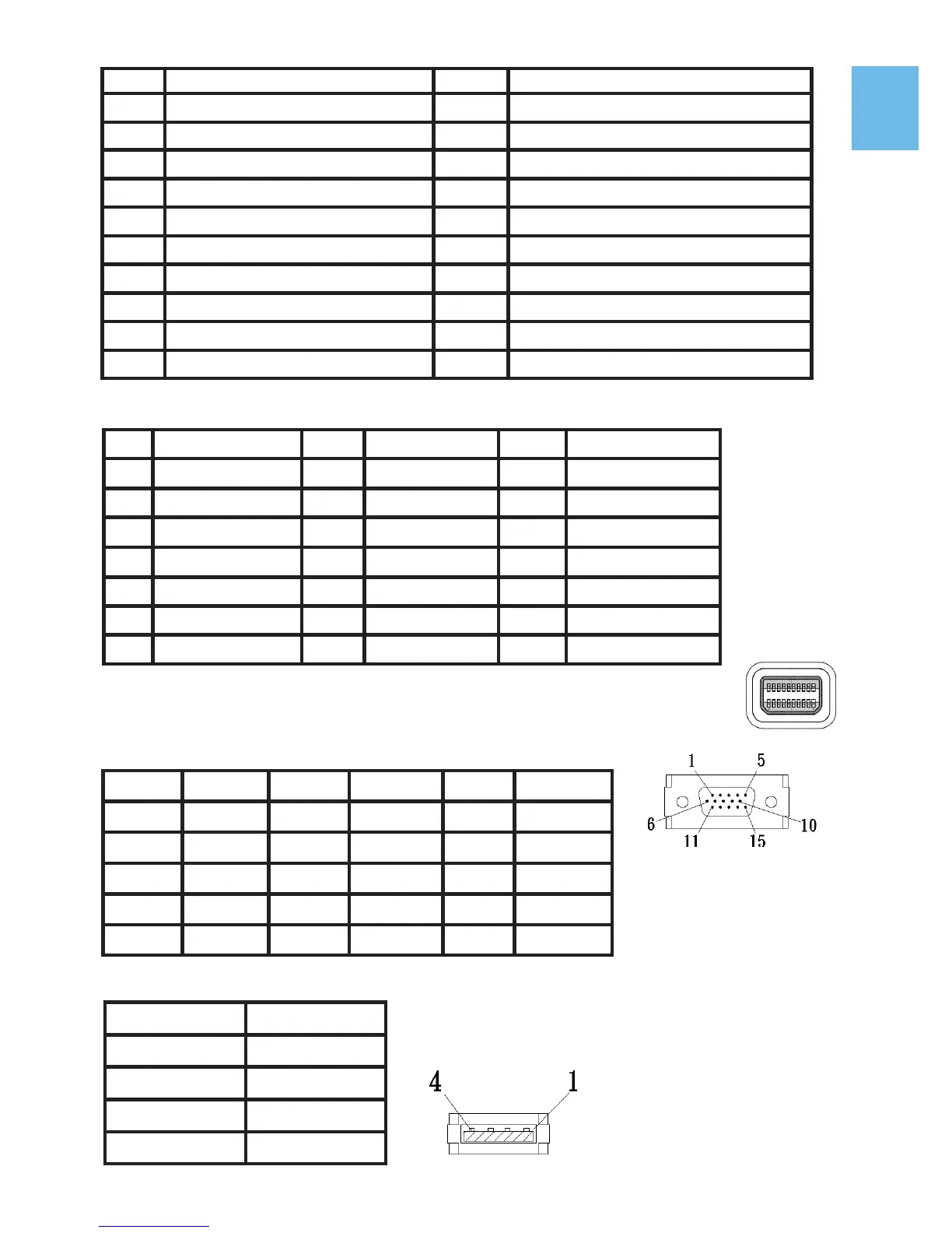
2. mini-DisplayPort Connector Pinout
3. VGA Connector Pinout
4. USB Connector Pinout
14
Pin Name Pin Name Pin Name
1 GND 8 GND 15 ML_Lane2(p)
2 Hot Plug Detect 9 ML_Lane1(p) 16 AUX_CH(p)
3 ML_Lane0(p) 10 ML_Lane3(p) 17 ML_Lane2(n)
4 CONFIG1 11 ML_Lane1(n) 18 AUX_CH(n)
5 ML_Lane0(n) 12 ML_Lane3(n) 19 GND
6 CONFIG2 13 GND 20 DP PWR
7 GND 14 GND
Pin : mini-DisplayPort Connector
(Connect mini-DisplayPort)
Pin No. Name Pin No. Name Pin No. Name
1 RED 6 RGND 11 NC
2 GREEN 7 GGND 12 SDA
3 BLUE 8 BGND 13 HSYNC
4 NC 9 +5V 14 VSYNC
5 GND 10 SGND 15 SCL
Fig.: VGA connector
(connect to PC’s
VGA port)
Pin No. Name
1 Vcc (+5V)
2 D+
3 D-
4 Ground
Fig .: USB Connector
Pin Name Pin Name
1 TMDS Data2+ 11 TMDS Clock Shield
2 TMDS Data2 Shield 12
TMDS Clock –
3 TMDS Data2 – 13
CEC
4 TMDS Data1+ 14
Reserved
5 TMDS Data1 Shield 15 SCL (I²C Serial Clock for DDC)
6 TMDS Data1 – 16 SDA (I²C Serial Data Line for DDC)
7 TMDS Data0+ 17 DDC/CEC Ground
8 TMDS Data0 Shield 18 +5 V Power
9 TMDS Data0 – 19 Hot Plug Detect
10 TMDS Clock+