MC34067, MC33067
http://onsemi.com
4
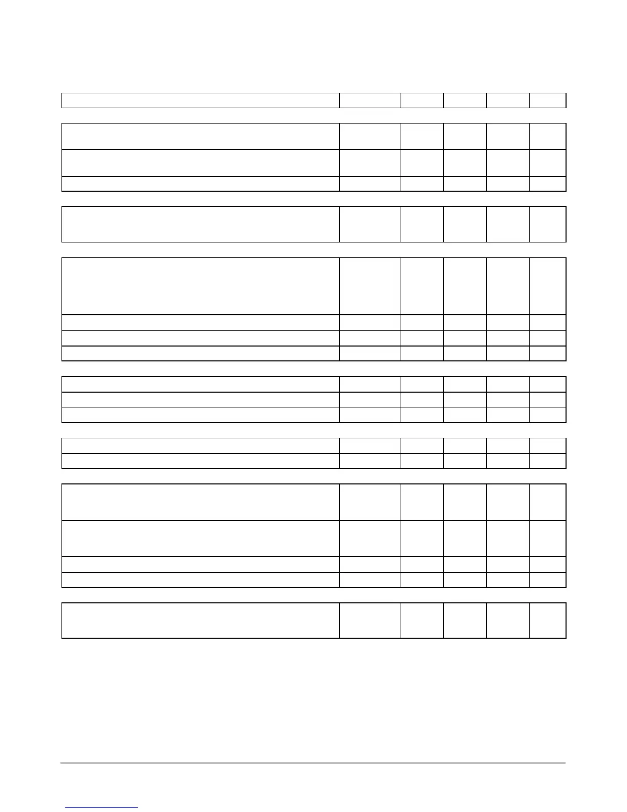
ELECTRICAL CHARACTERISTICS (continued) (V
CC
= 12 V [Note 6], R
OSC
= 18.2 k, R
VFO
= 2940 W, C
OSC
= 300 pF,
R
T
= 2370 W, C
T
= 300 pF, C
L
= 1.0 nF. For typical values T
A
= 25°C, for min/max values T
A
is the operating ambient temperature range
that applies (Note 7), unless otherwise noted.)
Characteristic
Symbol Min Typ Max Unit
OSCILLATOR
Frequency (Error Amp Output Low)
Total Variation (V
CC
= 10 V to 18 V, T
A
= T
Low
to T
High
) f
OSC(low)
490 525 550
kHz
Frequency (Error Amp Output High)
Total Variation (V
CC
= 10 V to 18 V, T
A
= T
Low
to T
High
) f
OSC(high)
1850 2050 2200
kHz
Oscillator Control Input Voltage, Pin 3 V
in
− 2.5 − V
ONE−SHOT
Drive Output Off−Time
T
A
= 25°C
Total Variation (V
CC
= 10 V to 18 V, T
A
= T
Low
to T
High
)
t
Blank
235
225
250
−
270
280
ns
DRIVE OUTPUTS
Output Voltage
Low State (I
Sink
= 20 mA)
Low State (I
Sink
= 200 mA)
High State (I
Source
= 20 mA)
High State (I
Source
= 200 mA)
V
OL
V
OH
−
−
9.5
9.0
0.8
1.5
10.3
9.7
1.2
2.0
−
−
V
Output Voltage with UVLO Activated (V
CC
= 6.0 V, I
Sink
= 1.0 mA) V
OL(UVLO)
− 0.8 1.2 V
Output Voltage Rise Time (C
L
= 1.0 nF) t
r
− 20 50 ns
Output Voltage Fall Time (C
L
= 1.0 nF) t
f
− 15 50 ns
FAULT COMPARATOR
Input Threshold V
th
0.93 1.0 1.07 V
Input Bias Current (V
Pin
10
= 0 V) I
IB
− − 2.0 − 10
mA
Propagation Delay to Drive Outputs (100 mV Overdrive) t
PLH(In/Out)
− 60 100 ns
SOFT−START
Capacitor Charge Current (V
Pin
11
= 2.5 V) I
chg
4.5 9.0 14
mA
Capacitor Discharge Current (V
Pin
11
= 2.5 V) I
dischg
3.0 8.0 − mA
UNDERVOLTAGE LOCKOUT
Startup Threshold, V
CC
Increasing
Enable/UVLO Adjust Pin Open
Enable/UVLO Adjust Pin Connected to V
CC
V
th(UVLO)
14.8
8.0
16
9.0
17.2
10
V
Minimum Operating Voltage After Turn−On, V
CC
Decreasing
Enable/UVLO Adjust Pin Open
Enable/UVLO Adjust Pin Connected to V
CC
V
CC(min)
8.0
7.6
9.0
8.6
10
9.6
V
Enable/UVLO Adjust Shutdown Threshold Voltage V
th(Enable)
6.0 7.0 − V
Enable/UVLO Adjust Input Current (Pin 9 = 0 V) I
in(Enable)
− − 0.2 − 1.0 mA
TOTAL DEVICE
Power Supply Current (Enable/UVLO Adjust Pin Open)
Startup (V
CC
= 13.5 V)
Operating (f
OSC
= 500 kHz) (Note 6)
I
CC
−
−
0.5
27
0.8
35
mA
5. Maximum package power dissipation limits must be observed.
6. Adjust V
CC
above the Startup Threshold voltage before setting to 12 V.
7. Low duty cycle pulse techniques are used during test to maintain junction temperature as close to ambient as possible.
8. T
low
=0°C for MC34067
= − 40°C for MC33067
T
high
=+70°C for MC34067
=+85°C for MC33067