MC34067, MC33067
http://onsemi.com
7
3
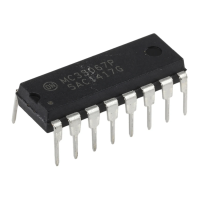
Figure 14. MC34067 Representative Block Diagram
12
Output B
13
14
8
7
Inverting Input
Oscillator
Control Current
16
9
8.0 V
Q2
R
R
T
C
T
R
OSC
C
OSC
R
VFO
V
ref
4.9V/3.6 V
15
V
CC
Enable /
UVLO Adjust
OSC Charge
OSC RC
One-Shot RC
Error Amp Output
Noninverting Input
Soft-Start
Ground4
Fault Input
Power
Ground
Output A
V
ref
D1
Q1
I
OSC
Oscillator
One-Shot
Error Amp
Clamp
3.1V
Error Amp
9.0 mA
1.0 V
Q
Q
T
Steering
Flip-Flop
4.2/4.0 V
V
ref
UVLO
V
CC
UVLO
7.0k
50k 7.0k
50k
4.9 V/3.6 V
V
ref
5.1 V
Reference
1
2
6
11
5
10
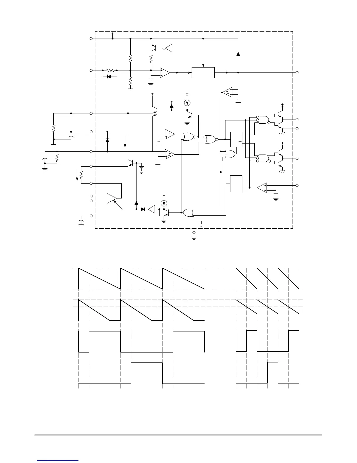
Figure 15. Timing Diagram
5.1 V
3. 6 V
C
OSC
5.1 V
3.6 V
One-Shot
Output A
Output B
t
OS
t
OS
t
OS
t
OS
t
OS
t
OS
High State Error Amp output, minimum I
OSC
current
occurring at minimum input voltage, maximum load.
Low State Error Amp output, maximum I
OSC
current
occurring at maximum input voltage, minimum load.
Fault Comparator
I
OSC
Fault
Latch
S
R
Q