WATER
PUMPS
#132-0110
and
#132-0074
Pumps #132-0110 and #132-0074 are centrifugal
pumps with metal impellers (Figure 19).
Disassembly
1.
2.
3.
4.
Remove the water inlet fitting, drive belt pulley,
cover screws, and pump cover gasket.
Unscrew the threaded impeller from the pump
shaft by turning the impeller
in
a counterclock-
wise direction (when facing impeller).
Slide the seal seat, wear face, and bellows
assembly
off
the shaft. Loosen the clamp screw
and slide the pump body
off
the pedestal.
Remove the bearing lock ring and drive the shaft
and bearing assembly out of the pedestal. The
bearing is press fit on the shaft and comes
off
in
one integral part. The bearing is packed with
a
lifelong lubricant and is sealed at each end.
Assembly
i
Replace all worn components such as bearings,
seals, wear face, and impeller and use a new cover
gasket. Assembly sequence is the reverse of the dis-
assembly procedure.
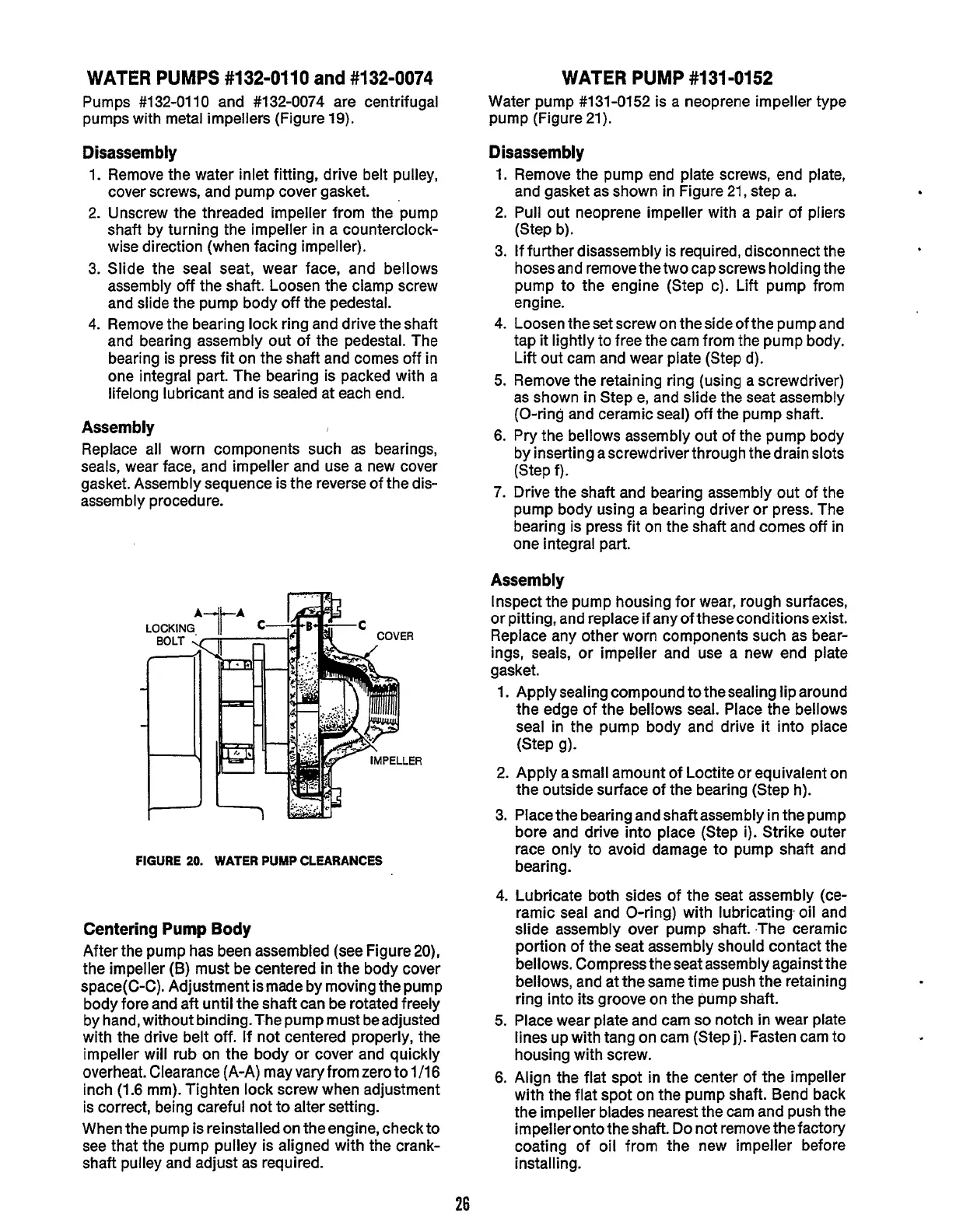
FIGURE
20.
WATER
PUMP
CLEARANCES
Centering
Pump
Body
After the pump has been assembled (see Figure
20),
the impeller
(B)
must be centered in
the
body cover
space(C-C). Adjustment ismade by moving the pump
body fore and aft until the shaft can be rotated freely
by hand, without binding.The pump must beadjusted
with the drive belt
off.
If not centered properly, the
impeller
will
rub on the body or cover and quickly
overheat. Clearance (A-A) may vary from zero
to
1/16
inch (1.6 mm). Tighten lock screw when adjustment
is correct, being careful not to alter setting.
When the pump is reinstalled on the engine, checkto
see that the pump pulley is aligned with the crank-
shaft pulley and adjust as required.
WATER
PUMP
#131-0152
Water pump #131-0152 is a neoprene impeller type
pump (Figure 21).
Disassembly
1.
2.
3.
4.
5.
6.
7.
Remove the pump end plate screws, end plate,
and gasket as shown in Figure
21,
step a.
Pull out neoprene impeller with a pair of pliers
(Step b).
If further disassembly is required, disconnect the
hoses and remove the two cap screws holding the
pump to the engine (Step c). Lift pump from
engine.
Loosen the set screw on the side of
the
pump and
tap
it
lightly to free the cam from the pump body.
Lift
out cam and wear plate (Step d).
Remove the retaining ring (using a screwdriver)
as shown in Step e, and slide the seat assembly
(O-ring and ceramic seal)
off
the pump shaft.
Pry the bellows assembly out of the pump body
by inserting ascrewdriver through the drain slots
(Step f).
Drive the shaft and bearing assembly out of the
pump body using a bearing driver or press. The
bearing is press fit on the shaft and comes
off
in
one integral part.
Assembly
Inspect the pump housing for wear, rough surfaces,
or pitting, and replace if any of theseconditionsexist.
Replace any other worn components such as bear-
ings, seals, or impeller and use a new end plate
gasket.
1.
Apply sealing compound to the sealing lip around
the edge of the bellows seal. Place the bellows
seal in the pump body and drive
it
into place
2. Apply a small amount of Loctite or equivalent on
the outside surface
of
the bearing (Step h).
3. Place the bearing and shaft assembly in the pump
bore and drive into place (Step i). Strike outer
race only to avoid damage to pump shaft and
bearing.
4. Lubricate both sides of the seat assembly (ce-
ramic seal and O-ring) with lubricating oil and
slide assembly over pump shaft. ,The ceramic
portion of the seat assembly should contact the
bellows. Compress the seat assembly against the
bellows, and at the same time push the retaining
ring into its groove on the pump shaft.
5.
Place wear plate and cam
so
notch
in
wear plate
lines up with tang on cam (Step j). Fasten cam to
housing with screw.
6. Align
the
flat spot in the center of the impeller
with the flat spot on the pump shaft. Bend back
the impeller blades nearest the cam and push the
impeller onto the shaft.
Do
not remove the factory
coating of oil from the new impeller before
installing.
(Step 9)-
26
Redistribution or publication of this document,
by any means, is strictly prohibited.
 Loading...

