NOZZLE
REPAIR
If cleaning
will
not eliminate a nozzle defect, replace
the nozzle or take
it
to
an authorized diesel
service
station.
Do
not attempt to replace parts of the nozzle
except for nozzle and pintle assembly.
.
Assembly
Rinse both valve and nozzle thoroughly before
assembly and coat with diesel fuel. The valve must be
free in the nozzle.
Lift
it
about
1/3
out of the body.
It
should slide back to its seat with,out aid when the
assembly is held at a 45-degree angle. If necessary,
work the valve into its body with clean mutton tallow.
SOLENOID
.
WIRE
TO
CONTROL
1.
Clamp nozzle holder body in a vise.
2. Set valve in body and set nozzle over
it.
3.
Install nozzle cap nut loosely.
4. Place centering sleeve over nozzle for initial
tightening. Then remove centering sleeve to pre-
vent
it
from binding between nozzle and cap nut.
5.
Tighten nozzlecap nutto50-55ft.-lb. (68-75Nm).
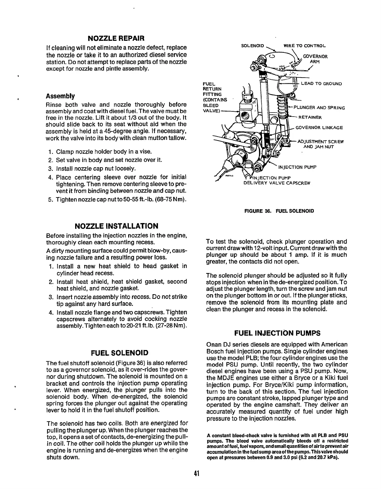
FIGURE
36.
FUEL SOLENOID
NOZZLE INSTALLATION
Before installing the injection nozzles in the engine,
thoroughly clean each mounting recess.
A dirty mounting surface could permit blow-by, caus-
ing nozzle failure and a resulting power
loss.
1.
Install a new heat shield
to
head gasket in
cylinder head recess.
2. Install heat shield, heat shield gasket, second
heat shield, and nozzle gasket.
3.
Insert nozzle assembly into recess.
Do
not strike
tip against any hard surface.
4.
Install nozzle flange and two capscrews. Tighten
capscrews alternately to avoid cocking nozzle
assembly. Tighten each to 20-21
ftlb.
(27-28 Nm).
FUEL SOLENOID
The fuel shutoff solenoid (Figure
36)
is also referred
to as a governor solenoid, as
it
over-rides the gover-
nor during shutdown. The solenoid is mounted on a
bracket and controls the injection pump operating
lever. When energized, the plunger pulls into the
solenoid body. When de-energized, the solenoid
spring forces the plunger out against the operating
lever to hold
it
in the fuel shutoff position.
The solenoid has two
coils.
Both are energized
for
pulling the plunger up. When the plunger reaches the
top,
it
opens a set
of
contacts, de-energizing the pull-
in coil. The other coil holds the plunger up while the
engine is running and de-energizes when the engine
shuts down.
To
test the solenoid, check plunger operation and
current draw with 12-volt input. Current draw with the
plunger up should be about
1
amp. If
it
is much
greater, the contacts did not open.
The solenoid plunger should be adjusted
so
it
fully
stops injection when in the de-energized position. To
adjust the plunger length, turn thescrew and jam nut
on
the
plunger bottom
in
or out. If the plunger sticks,
remove the solenoid from its mounting plate and
clean the plunger and recess
in
the solenoid.
FUEL INJECTION
PUMPS
Onan
DJ
series diesels are equipped with American
Bosch fuel injection pumps. Single cylinder engines
use the model PLB;
the
four cylinder engines use the
model PSU pump. Until recently, the two cylinder
diesel engines have been using a
PSU
pump. Now,
the
MDJE
engines use either a Bryce or a Kiki fuel
injection pump. For Bryce/Kiki pump information,
turn to the back of this section. The fuel injection
pumps are constant stroke, lapped plunger type and
operated by the engine camshaft. They deliver an
accurately measured quantity of fuel under high
pressure to the injection nozzles.
A
constant bleed-check valve
is
furnished with all PLB and PSU
pumps. The bleed valve automatically bleeds
off
a restricted
amount
of
fuel,
fuel
vapors, and
small
quantifies
of
air
to
prevent air
accumulation
in
the
fuel
sump areaof
thepumps.1hisvalveshould
open at pressures between
0.9
and
3.0
psi
(6.2
and
20.7
kPa).
41
Redistribution or publication of this document,
by any means, is strictly prohibited.
 Loading...

