BELT DRIVEN
(35
AMP) BATTERY
CHARGING ALTERNATOR
(Optional)
This information is presented for field useonly. Major
repair should be done in the shop.
Brush
Assembly Removal
Remove brushes as follows:
1.
Remove three screws which fasten voltage regu-
lator to alternator.
2.
Disconnect regulator leads and remove regulator.
3.
Remove two screws on phenolic cover and lift out
4.
Pull brush assembly straight up and lift out.
cover and gasket.
5.
Reverse procedure for assembly (Figure
99).
Brush
Assembly
Tests
Test brush assembly as
follows:
1.
Connect an ohmmeter or test lamp (12 volts) to
the field terminal and
to
the bracket. The test
lamp should not light or resistance reading should
be
high (infinite). If not, there
is
a short and the
assembly must be replaced.
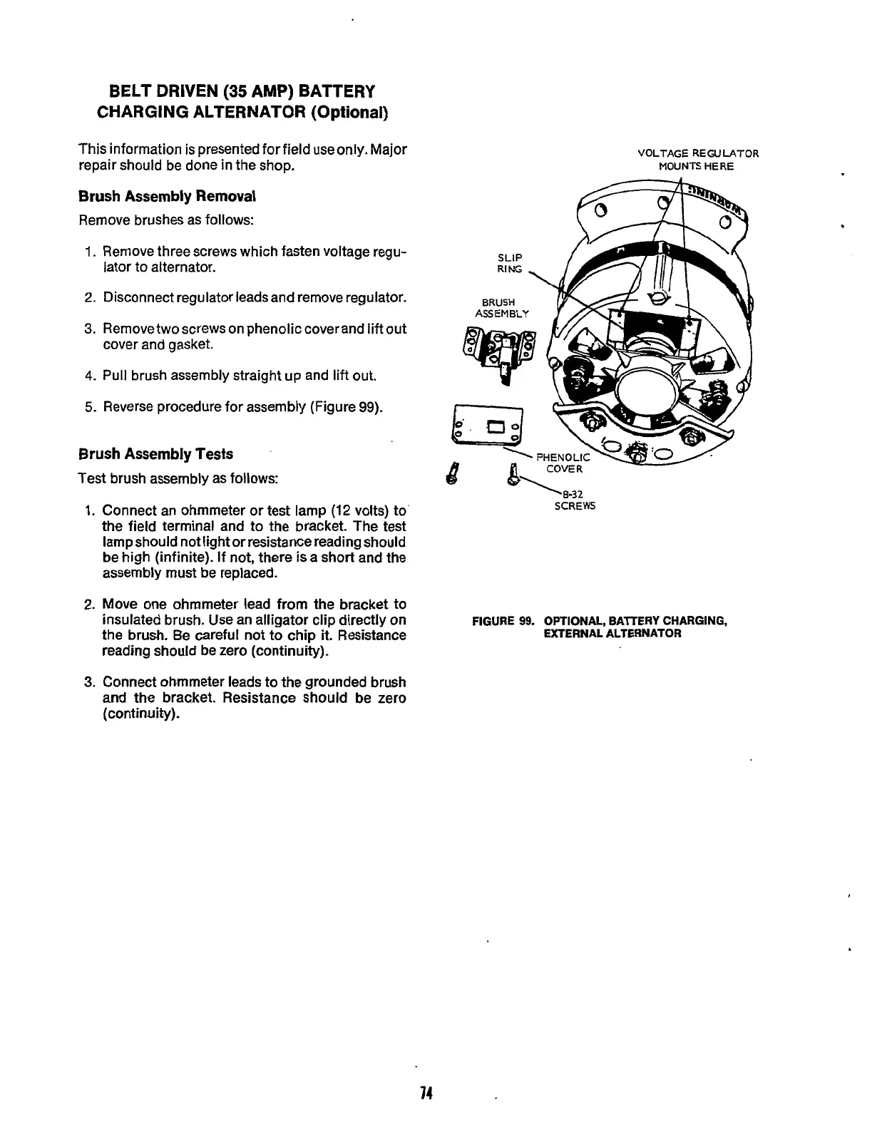
VOLTAGE REGULATOR
MOUNTS HERE
‘8-32
SCREWS
2.
Move one ahrnmeter lead from the bracket to
insulated brush. Use an alligator clip directly on
the brush.
Be
careful not to chip
it.
Resistance
FIGURE
99.
OPTIONAL, BAlTERY
CHARGING,
EXTERNAL ALTERNATOR
reading should be zero (continuity).
3.
Connect ohmmeter leads to the grounded brush
and the brac.ket. Resistance should
be
zero
(continuity).
74
Redistribution or publication of this document,
by any means, is strictly prohibited.
 Loading...

