Removal and Disassembly
On 2- and 4-cylinder engines, the connecting rod and
cap arestamped for installation in the proper cylinder.
When removing piston assemblies, check the mark-
ing
so
each can be installed in the proper cylinder.
1.
Drain crankcase oil and remove oil base.
2. Remove cylinder heads.
3.
Before pushing pistons out, scrape carbon at top
of cylinder bore.
4.
Remove cap from each connecting rod and push
assembly through top of cylinder bore. Replace
cap and bearing inserts in proper assembly.
5.
Using a ring expander, remove rings from each
piston.
6. Remove two retaining rings and push piston pin
from each piston.
Cylinders
The cylinder walls should be free of scratches, pit-
ting, and scuffing. Check each with an inside reading
micrometer for out-of-round and wear. The bore
measurement should beasspecified and be less than
0.001 inch (0.0254 mm) out-of-round.
If necessary, rebore the cylinder to fit the next availa-
ble oversize piston. Pistons and rings are available in
0.005, 0.010, 0.020, 0.030, and 0.040 inch (0.127,
2.540,0.508,0.762,1.016 mm) oversize. If the cylind-
ers do not need refinishing; remove any existing
ridges from
the
top of the walls with a fine stone.
Pistons
Clean thoroughly and inspect each piston. Clean the
carbon from the ring grooves and be sure all oil holes
are open. If any piston is badly scored or burred,
loose in the cylinder, has badly worn ring grooves or
otherwise is not in good condition, replace
it.
See
Figure
109.
Install pistons with valve relief recess
facing the camshaft side of engine
to match valve positions.
Check the clearances 90 degrees from the axis of the
piston pin and below the oil control ring. Clearance
should be
0.005
to 0.007 inch (0.127 to
0.178
mm).
If
not, replace the piston and check the cylinder for
possible reconditioning.
PISTON PINS
Each piston pin should be a thumb push fit into its
piston at room temperatures. If the pin is excessively
loose, install a new one. If
the condition is not cor-
rected, install the next oversize pin. If
the
piston is
worn enough
so
that the oversize pin will not fit,
replace it.
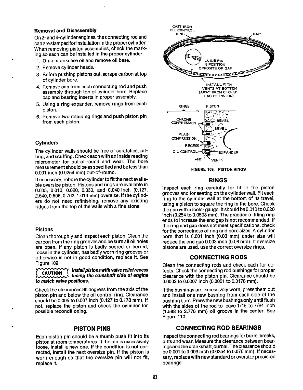
CAST
IRON
OIL CONTROL
IN
POSITION
-\--
~
INSTALL WITH
VENTS AT BOTTOM
(AWAY
FROM
CLOSED
END
OF
PISTON)
RINGS
PISTON
'
'
VENTS
FIGURE
109.
PISTON
RINGS
RINGS
Inspect each ring carefully for fit in the piston
grooves and for seating on the cylinder wall. Fit each
ring to the cylinder wall at the bottom of its travel,
using a piston to square the ring
in
the bore. Check
thegap with afeeler gauge.
It
should beO.O1O to0.020
inch (0.254 to
0.0508
mm). The practice of filing ring
ends to increase the end gap is not recommended. If
the ring end gap does not meet specifications, check
for the correctness of ring and bore sizes.
A
cylinder
bore that is
0.001
inch
(0.03
mm) under size will
reduce the end gap
0.003
inch
(0.08
mm). If oversize
pistons are used, use the correct oversize rings.
CONNECTING RODS
Clean the connecting rods and check each for de-
fects. Check the connecting rod bushings for proper
clearance with the piston pin. Clearance should be
0.0002 to 0.0007 inch (0.0051 to 0.0178 mm).
If the bushings are excessively worn, press them out
and install one new bushing from each side
of
the
bushing bore. Pressthenew bushingsonly until flush
with the sides of
the
rod to leave 1/16 to 7/64 inch
(1.588 to 2.776 mm) oil groove in the center. See
Figure 110.
CONNECTING ROD BEARINGS
Inspect the connecting rod bearings for burrs, breaks,
pitts and wear. Measure the clearance between bear-
ings and thecrankshaftjournaLThe clearanceshould
be
0.001
to
0.003
inch (0.0254 to 0.076 mm).
If
neces-
sary, replace with new standard or oversize precision
bearings.
83
Redistribution or publication of this document,
by any means, is strictly prohibited.
 Loading...

