6.
When disassembling engine,
mike
bearing plate
gasket thickness. Then select proper shim
thickness for correct end play.
Shims establish end play. Only one thickness gasket
is
included in kit.
7.
When assembling crankshaft, make sure bearing
thrust washers are in proper position supported
by bearing stop pins. Use cup grease to hold in
place.
8.
When adjusting valve lash, tap rocker arm
so
it
is
straight when checking with feeler gauge.
9.
Crank gears are easier to remove and install if
heated a slight amount.
Do
not overheat
or
temper may
be lost and shaft may expand.
10.
See FUEL SYSTEM section for correct engine
timing.
11.
Allow some gear lash (approximately 0.005-inch)
in oil pump. Do
not install gears tightly against
each other!
TESTING AND ADJUSTING ENGINES
Preparation
Check the following:
1.
Put proper oil
in
crankcase.
2.
Service air cleaner.
3.
Connect fuel line.
4. Connect load.
5.
Connect fully charged battery.
6.
Check ventilation for proper cooling.
OPERATION
1.
Start engine
-
(see
Diesel Starting Guide).
2.
Check oil pressure.
3.
Run unit
15
minutes to bring up to operating
ternperatu re.
4. Check for oil leaks, loose electrical connections,
tight fuel lines and tight exhaust connections.
.
ADJUSTMENTS
Adjust governor for speed and sensitivity.
IMPORTANT For complete customer satisfaction, repaint unit
(Onan Green, spray can 525-0137, or Onan White, spray can 525-
0216) and apply instructions from Kit 98-11OOC or Marine Kit 98-
1807.
CYLINDER HEADS, VALVES
Each cast iron cylinder head assembly has alloy
hard en ed -f aced valves, re
I
ease-ty p e rotators, al
I
oy
hardened inserts, guides, rocker arms, injection
nozzles and glow plugs.
Maintenance:
Check the valve clearances at regular intervals (see
SERVICEAND MAlNTENANCEsection).
In
addition,
clean the combustion chambers and valve seats as
required if engine loses power or has
low
compres-
sion.
VALVE CLEARANCE ADJUSTMENTS
The valves are adjusted cold. Afterthecooling period,
adjust
No.
1
cylinder first and the rest
in
the firing
order.
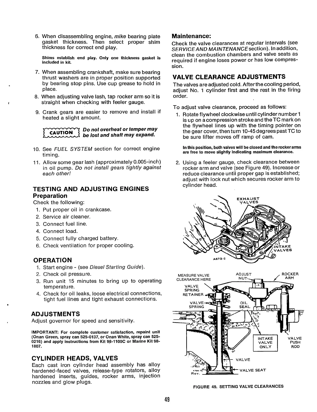
To adjust valve clearance, proceed as follows:
1.
Rotate flywheel clockwise until cylinder number
1
is up on acompression stroke and theTC mark on
the flywheel lines up with the timing pointer on
the gear cover, thenturn 10-45degreespastTCto
be sure lifter moves off ramp of cam.
In this position, both valves will be closed and the rockeranns
are free to move slightly indicating maximum clearance.
2.
Using a feeler gauge, check clearance between
rocker arm and valve (see Figure
49).
Increase or
reduce clearance until proper gap is established;
adjust with lock nut which secures rocker arm to
cy1
i
nder head.
-\
EXHAUST
RETAINER
d
FIGURE 49. SETTING VALVE CLEARANCES
49
Redistribution or publication of this document,
by any means, is strictly prohibited.