3.
4.
5.
6.
7.
8.
To adjust valve clearance for number 2 cylinder,
turn flywheel
in
a clockwisedirection 180degrees
(1/2 revolution) from position used in Step
1.
The
flywheel position should be between 10 degrees
and 45 degrees past the bottom center (BC).
IMPORTANT:
Four-cylinder engines
do
not have a
BC
mark
on the flywheel.
After timing number 2 cylinder, adjust valve
clearance according
ta
step 2.
To adjust valve clearance for number 4 cylinder,
turn flywheel
in
a clockwisedirection 180degrees
(1/2 revolution). The flywheel should be between
lodegreesand 45degrees past flywheel TC mark.
After timing number 4 cylinder, adjust valve
clearance according to Step 2.
To adjust valve clearance for number 3 cylinder,
turn flywheel in a clockwise direction
1
80 degrees
(1/2 revolution). The flywheel should be between
10 degrees and 45 degrees past BC.
After timing number 3 cylinder, adjust valve
clearance according to Step 2.
Repair:
Thoroughly clean all components of the cylinder
head assemblies. Remove all the carbon deposits
from the intake and exhaust ports and clean all gasket
surfaces.
Valves:
Remove all carbon and check each valve for
burning, pitting, or a warped stem. Refinish valves
that are slightly pitted or burned on an accurate valve
grinder. Refinish intake valves to a 42 degree angle
and exhaust valves to a 45 degree angle. If they are
badly pitted or have a thin edge when refacing,
replace them.
Check refinished valves for a tight seat to the valve
seat with an air-pressure-type testing tool or by
applying Prussian Blue on the valve face and rotating
it against the seat.
Valve Guides:
Check valve guide to valve clearance.
See the
DIMENSIONSAND CLEARANCES
section.
If
the proper clearances cannot be obtained by replac-
ing the valves, replace the valve auides. Drive the old
-
-
valve guides into the valve chambers. Drive new
guides in until they protrude 11/32 inch (8.731 mm)
from the rocker box side of the head. Ream the new
valve guide to obtain the proper clearance.
Testing:
The cylinder compression test can be used to deter-
mine the condition of valves, pistons, piston rings,
and cylinders.
To check compression, run the engine until thor-
oughly warm. Stop engine and remove all injection
nozzles. Insert the compression gauge in one nozzle
hole. Crank the engine and note the reading.
Compression of a standard new engine cranking at
about 300 rpm is about 350-400 psi (2415 to
2760 kPa). RDJC prior to Spec P300-350 psi (2068 to
241 3 kPa). Compression should be fairly uniform,
normally with less than 30 psi (207 kPa) difference
between the highest and lowest cylinder, taken at the
same cranking rpm.
Compression readings may deviate from the above
readings because
of
differences in cranking speed,
altitude and ambient temperature conditions. There-
fore the specification is given only as a guide. The
best indication of leakage is the pressure difference
between cylinders.
Disassembly:
Keep rocker arms, rocker arm nuts, push rods and tappets in order,
so
they
go
back in the same valve train position.
1. Remove rocker box cover, fuel nozzles and
connecting oil lines to cylinder heads.
2. Remove intake and exhaust manifold.
3. Remove cap screws holding each cylinder head
to cylinder block.
4. Remove each head. If it sticks, rap it sharply with a
soft hammer.
Do
not use a pry.
5.
Remove rocker arms and push rods.
6. Using a valve spring compressor, disassemble the
valve assemblies.
Valve Seats:
If the valve seats are pitted, refinish
them. Using conventional seat-grinding equipment,
reface each seat to a 45 degree angle and a seat width
of 0.047 inch to 0.062 inch (1.19 to
1.57
mm). You
should be able to reface each seat several times
before
it
becomes necessary to replace
it.
If the valve seats are loose or cannot be refaced,
replace them.
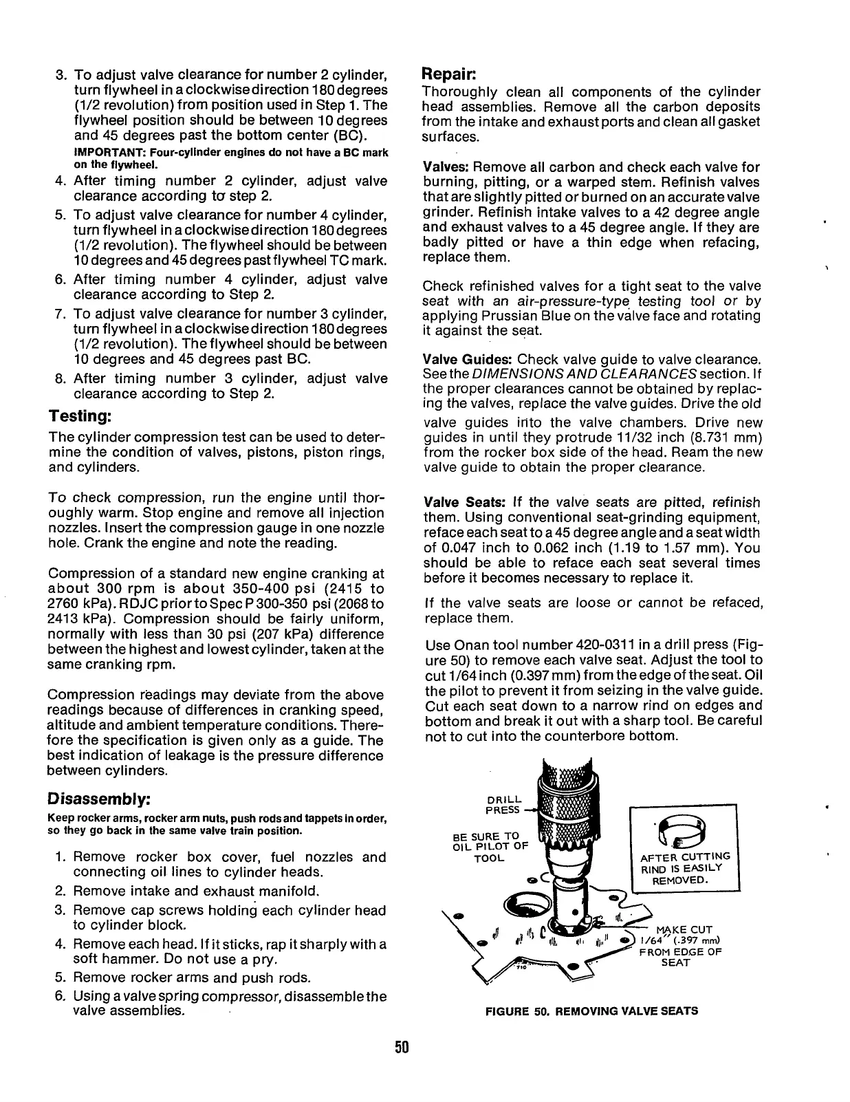
Use Onan tool number 420-031
1
in a drill press (Fig-
ure
50)
to remove each valve seat. Adjust the tool to
cut 1/64inch (0.397mm)from theedgeoftheseat. Oil
the pilot to prevent it from seizing in the valve guide.
Cut each seat down
to
a narrow rind on edges and
bottom and break it out with a sharp tool. Be careful
not to cut into the counterbore bottom.
FROM
EDGE OF
FIGURE
50.
REMOVING VALVE
SEATS
50
Redistribution or publication of this document,
by any means, is strictly prohibited.