Thoroughly clean the valve seat counterbore and
remove any burrs from the edges. If the counterbore
is
damaged,
it
will have to be machined foran oversize
seat. Oversize seats are available
in
0.002 inch,
0.005
inch,
0.010
inch and 0.025 inch (0.58,0.056,0.068. and
0.09
mm). Otherwise, install new standard size seat
inserts.
Drive the new valve seat inserts into place. Be certain
that each seat rests solidly on the bottom of the
counterbore at all points. To make installation easier,
heat the cylinder head in an oven at 325" F (162" C) for
about 1/2 hour and cool the valve seats in dry ice.
Face each new seat to a 45 degree angle and a width
of approximately 3/64 inch
(1.191
mm). The finished
seat face should contact the approximate center of
the valve face. Use Prussian
BI
ue on each valve face to
check this. Make any corrections on the seat, not the
valve face.
<
.
When the new seats are installed and faced, insert the
valve into each, and check the clearance from the
valve head to the face of the cylinder head. This must
be at least
0.030
inch (0.762 mm). If it is not, regrind
the seat.
Valve
Springs:
Check thevalve springson an accurate
compression scale. Valve spring data is given
in
the
DIMENSIONS AND CLEARANCES
section. Replace
any spring that is weak, cracked or pitted, or has ends
out-of-square.
VALVE AND HEAD ASSEMBLY
Installation
1.
2.
3.
4.
5.
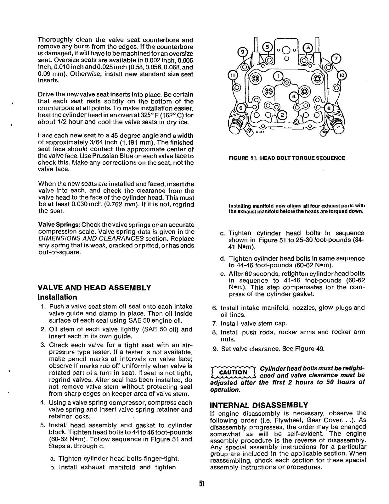
FIGURE
51.
HEAD BOLT TORQUE SEQUENCE
Installing manifold now aligns all four exhaust ports with
the exhaust manifold before the heads are torqued down.
c.
Tighten cylinder head bolts
in
sequence
shown
in
Figure
51
to 25-30 foot-pounds (34-
41
Nom).
d. Tighten cylinder head bolts in same sequence
to 44-46 foot-pounds (60-62 Nom).
e. After 60 seconds, retighten cylinder head bolts
in
sequence to 44-46 foot-pounds (60-62
Nom). This step compensates for the com-
press of the cylinder gasket.
Push a valve seat stem oil seal onto each intake
valve guide and clamp in place. Then oil inside
surface of each seal using SAE
50
engine oil.
Oil stem of each valve lightly (SAE
50
oil) and
insert each in its own guide.
6. Install intake manifold, nozzles, glow plugs and
7. Install valve stem cap.
8. Install push rods, rocker arms and rocker arm
oil lines.
nuts.
9.
Set valve clearance. See Figure
49.
Check each valve for a tight seat with an air-
Dressure tvDe tester. If a tester is not available,
make peniil marks at intervals on valve face;
observe if marks rub off uniformly when valve is
Cylinder head bolfs
must
be refighf-
rotated part of a turn
in
seat. If seat is not tight,
ened and valve clearance
musf
be
regrind valves. After seal has been installed, do
affer
the hours
50
hours
of
not remove valve stem without protecting seal
from sharp edges on keeper area of valve stem.
CAUT'oN
Using a valve spring compressor, compress each
valve spring and insert valve spring retainer and
retainer locks.
Install head assembly and gasket to cylinder
block. Tighten head bolts to 44 to 46foot-pounds
(60-62 Nom). Follow sequence in Figure
51
and
Steps a. through
c.
a. Tighten cylinder head bolts finger-tight.
b. Install exhaust manifold and tighten
INTERNAL DISASSEMBLY
If engine disassembly is necessary, observe the
following order (i.e. Flywheel, Gear Cover..
.).
As
disassembly progresses, the order may be changed
somewhat as will be self-evident. The engine
assembly procedure is the reverse of disassembly.
Any special assembly instructions for a particular
group are included
in
the applicable section. When
reassembling, check each section for these special
assembly instructions or procedures.
51
Redistribution or publication of this document,
by any means, is strictly prohibited.