EasyManua.ls Logo

Onkyo DX-6830 - Page 13

Onkyo DX-6830
24 pages
Print Icon
To Next Page IconTo Next Page
To Previous Page IconTo Previous Page
Loading...
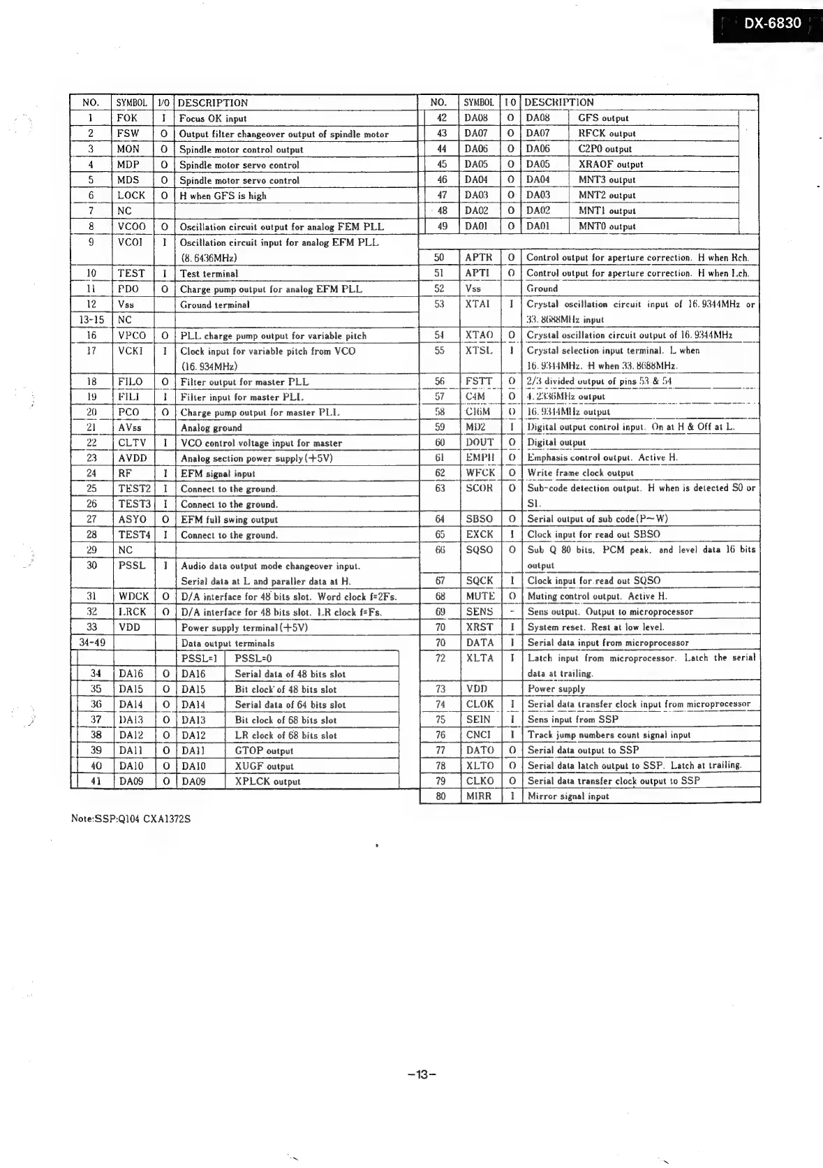
NO.
|
SYMBOL
|
1/0
-
7}
oO
nm
DX-6830
gle
teal
shale
bales
DESCRIPTION
NO.
|
SYMBOL
|
1-0
DESCRIPTION
Focus
OK
input
|]
42
|
DAs
DAG
_|_GFS
output
Output
filter
changeover
output
of
spindle
motor
|
43
DA07
RFCK
output
Spindle
motor
control
output
|
44
DAO06
C2P0
output
Spindle
motor
servo
control
|
45
DAOS
|
XRAOF
output
Spindle
motor
servo
control
{46
|
|
O
|
DAO
MNT3
output
:
H
when
GFS
is
high
||
47
0
|
DA03
|
_MNT2
output
|
|
48
0
|
DAQ2
|
MNTI
output
Oscillation
circuit
output
for
analog
FEM
PLL
|
49
|
DAO]
O
|
DAN
MNTO
output
Oscillation
circuit
input
for
analog
EFM
PLL
(8.
6436MHz)
Test
terminal
APTR
APTI
O
|
Control
output
for
aperture
correction.
H
when
ch.
Charge
pump
output
for
analog
EFM
PLL
Ground
terminal
Ground
33.
8688MHz
input
PLL
charge
pump
output
for
variable
pitch
Clock
input
for
variable
pitch
from
VCO
(16.
934MHz)
Filter
output
for
master
PLL
Filter
input
for
master
PLL.
Charge
pump
output
for
master
PLL
sof
“Crystal
oscillation
circuit
input
of
16.9344MHz
O
|
Crystal
oscillation
circuit
output
of
16.
9344MHz
or
Crystal
selection
input
terminal.
L
when
|
16.
9314MHz.
H
when
33.
8688MHz.
oO
2/3
divided
output
of
pins
53
&
of
4.
2336MHz
output
©
|
16.
9344MHz
output
Analog
ground
VCO
control
voltage
input
for
master
Analog
section
power
supply
(+5V)
MbD2
I
Digital
output
control
input.
On
at
H
&
Off
at
L.
=|
DOUT
O
|
Digital
output
©
|
Emphasis
control
output.
Active
H.
EMDHL
EFM
signal
input
[week
Connect
to
the
ground.
Connect
to
the
ground.
EFM
full
swing
output
Connect
to
the
ground.
Audio
data
output
mode
changeover
input.
Serial
data
at
L
and
paraller
data
at
H.
Serial
data
of
48
bits
slot
SCOR
Bit
clock’
of
48
bits slot
O
Write
frame
clock
output
©
|
Sub-code
detection
output.
H
when
is
detected
SQ
or
Sl.
System
reset.
Rest
at
low
level.
Serial
data
input
from
microprocessor
Latch
input
from
microprocessor.
Latch
the
serial
data
at
trailing.
Power
supply
Serial
data
of
64
bits
slot
Bit
clock
of
68
bits
slot
LR
clock
of
68
bits
slot
Sens
input
from
SSP
Track
jump
numbers
count
signal
input
GTOP
output
XUGF
output
XPLCK
output
Note:SSP:Q104
CXA1372S
Serial
data
output
to
SSP
Serial
data
transfer
clock
output
to
SSP
‘|
Serial
data
latch
output
to
SSP.
Latch
at
trailing.
-13-
Mirror
signal
input