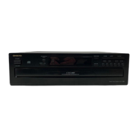
DX-C390
MAIN MICROPROCESSOR TERMINAL DESCRIPTION-1
80 pin QFP
Q701 : uPD784225GC
No. PIN NAME SIGNAL NAME I/O DESCRIPTION
1 P15/ANI5 GND I Not used. To connect GND pin.
2 P16/ANI6 GND I Not used. To connect GND pin.
3 P17/ANI7 GND I Not used. To connect GND pin.
4 AVss GND I GND
5 P130/ANO0 O Not used. Open pin.
6 P131/ANO1 O Not used. Open pin.
7 AVref1 +5V I Power supply pin for A/D port.
8 P70/SI2/RxD2 RXD I Received pin of RS232C mode.
9 P71/SO2/TxD2 TXD O Output pin of RS232C mode
10 P72/~SCK2/ASCK2 GND I Not used. To connect GND pin.
11 P20/SI1/RxD1 MSI I Data input pin from MP3 decoder and sub code data form CD processor.
12 P21/SO1/TxD1 MSO O Transmitting data output pin to MP3 decoder and command data of CD processor.
13 P22/~SCK1/ASCK1 MSCK O Decoder clock output pin. Communicate to MP3 decoder.
14 P23/PCL DOUT O Select the CD or MP3 output mode. L=MP3 H=CD
15 P24/BUZ SUBRST O Reset signal output pin.
16 P25/SI0/SDA0 SUBSO I Serial data input pin from sub microprocessor.
17 P26/SO0 SUBSI O Serial data output pin to sub microprocessor.
18 P27/~SCK0/SCL0 SUBCL O Serial clock output pin to sub microprocessor.
19 P40/AD0 CDSUBQ O Select the CD sub code output pin of serial port.
20 P41/AD1 CDCOM O Select the CD command output pin of serial port.
21 P42/AD2 MP3COM O Select the MP3 decoder output pin.
22 P43/AD3 MP3CE O Chip enable signal output pin of MP3 decoder.
23 P44/AD4 SENSI I Sens input pin for CD signal processor.
24 P45/AD5 CDXLT O Command latch output pin for CD signal processor.
25 P46/AD6 SCLKO O Sens reading clock output terminal to CD signal processor.
26 P47/AD7 FOKI I FOK signal input pin from signal processor.
27 P50/A8 LDON O Laser light control output pin. HiZ=OFF L=CD H=CD-RW
28 P51/A9 CDRESET O Reset pin of MP3 decoder.
29 P52/A10 CDPOWER O Power supply control pin.
30 P53/A11 CDMUT O Analog mute pin. H=OFF/L=ON
31 P54/A12 STOP_POS_SEN
I Detection the sensor input pin for disc position.
32 P55/A13 DISC_SENS I Disk existence detection optical sensor input terminal.
33 Vss1 GND I
34 P56/A14 ROT_R O Roulette motor control pin-R.
35 P57/A15 ROT_L O Roulette motor control pin-L.
36 P60/A16 ROTHI O Roulette motor speed control terminal..
37 P61/A17 LOADING_SW1 I Loading clamp position detection switch input terminal 1.
38 P62/A18 LOADING_SW2 I Loading clamp position detection switch input terminal 2.
39 P63/A19 LOADING_SW3 I Loading clamp position detection switch input terminal 3.
40 P64/~RD CURRENT I Loading clamp motor current detection input terminal.
41 P65/~WR LOADING_L O Loading clamp motor control terminal L.
42 P66/~WAIT LOADING_R O Loading clamp motor control terminal R.
43 P67/ASTB O Not used. Open pin.
44 P30/TO0 O Not used. Open pin.
45 P31/TO1 DITDI I The serial transmission data input terminal to DIT.
46 P32/TO2 DITDO O The serial transmission data output terminal to DIT.
47 P33/TI1 DITCL O The serial data transmission data output terminal to DIT.
48 P34/TI2 DITCE O The control command chip enable signal output terminal of DIT.
49 P35/TIO0 DITPD O DIT power down signal output terminal.
50 P36/TIO1 EEPROMCS O Chip select signal output pin of EEPROM.
51 P37/EXA EEPROMCLK O Serial clock signal output pin of EEPROM.
52 P120/RTP0 EEPROMDI O Serial data signal output pin to EEPROM.
53 P121/RTP1 EEPROMDO I Serial data signal input pin from EEPROM.
54 P122/RTP2 DACMUT O Digital mute signal of DAC. H=ON/L=OFF
GND
 Loading...