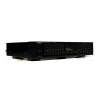
4.
Accessory
microphone
Battery
The
microphone
is
powered
by
a
battery.
Before
using
this
microphone
for
the
first
time.
insert
the
battery(included)
as
shown
in
the
diagram.
Whenever
the
microphone
is
not
in
use,
be
sure
to
set
its
ON/OFF
switch
to
OFF.
In
case
the
microphone
is
left
ON,
the
average
life
of
its
battery
is
about
500
hours.
The
battery
lasts
from
two
to
three
years
during
ordinary
use,
but
its
life
may
be
shorter
due
to
frequent
use
or
environmental
conditions
(temper-
ature
or
humidity).
If
no
microphone
output
can
be
obtained
or
noise
is
produced,
please
replace
the
battery
with
a
new
one
conforming
to
the
table
below.
B
Battery
Replacement
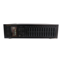
ADJUSTMENT
PROCEDURES
1.
Preparation
4.
Adjustment
of
distortion
of
oscillator
signal
Switch
position
(1)
Set
the
INPUT
SELECTOR
to
SPOT.
РОМЕК..............................
ON
(2)
Push
the
SHIFT
shift
to
1
KHz.
ЕОСАП/ЕК.........................
ОҒЕ
(3)
With
the
semi-fixed
resistor
VR302,
adjust
the
oscil-
EQ.
КАКСЕ.......................
+12dB
lator
output
(above
150mV)
so
that
the
distortion
SLIDER
LEDL,R..................200.
ON
factor
is
minimum.
INPUT
SELECTOR.
...................
LINE
5.
Adjustment
of
WARBLE
TONE
OSC.
СНІ,К.........................
ON
(1)
After
the
adjustment
of
Item
4,
turn
ON
the
WARBLE
METER
ТІҺРСГТ....................
SOURCE
switch.
PEAK
НОГО.........................
OFF
(2)
Adjust
the
semi-fixed
resistor
VR301
so
that
the
center
METER
LEVEL
...............-..
MAXIMUM
of
the
1KHz
waveform
of
the
oscillator
is
the
center
of
ATTENUATOR
................
0
(MAXIMUM)
the
abnormality.
ЕО.ІЕУЕГ.,...................
0
(СЕМТЕК)
Equal
condition
WARBLE
ON
2.
Adjustment
of
level
meter
sensitivity
(1)
Input
a
|
KHz,
15mV
signal
to
LINE
INPUT
Г.
(2)
With
the
semi-fixed
resistor
VR401,
align
the
indicator
tube
PEAK
LEVEL
meter
to
the
“O”
graduation.
(Move
up
from
below
and
stop
at
the
position
where
the
“0”
section
lights.)
3.
Adjustment
of
the
meter
L,
R
deviation
(1)
Input
a
ІКН?,
15mV
signal
to
both
L,
R
of
LINE
INPUT.
(2)
With
the
semi-fixed
resistor
VR115,
adjust
the
PEAK
LEVEL
meter
indication
until
they
are
the
same.
(Adjust
until
the
METER
LEVEL
movement
up/down
for
L,
R
deviation
is
minimum.)
 Loading...