EasyManua.ls Logo

Onkyo SKW-204(B) User Manual

Onkyo SKW-204(B)
11 pages
To Next Page IconTo Next Page
Page #1 background imageLoading...
Page #1 background image
SKW-204
SERVICE MANUAL
SERVICE MANUAL
POWERED SUBWOOFER
Black, Silver and Yellow models
MODEL SKW-204(B)/(S)/(Y)
Ref. No. 3946
052006
120V AC, 60Hz
230-240V AC, 50Hz
230-240V AC, 50Hz
B MDC
B MPP
S MPP
230-240V AC, 50Hz
120/220-240V AC, 50/60Hz
S MPA
S MWT
Y MWT
SAFETY-RELATED COMPONENT
WARNING!!
COMPONENTS IDENTIFIED BY MARK ON THE
SCHEMATIC DIAGRAM AND IN THE PARTS LIST ARE
CRITICAL FOR RISK OF FIRE AND ELECTRIC SHOCK.
REPLACE THESE COMPONENTS WITH ONKYO
PARTS WHOSE PART NUMBERS APPEAR AS SHOWN
IN THIS MANUAL.
MAKE LEAKAGE-CURRENT OR RESISTANCE
MEASUREMENTS TO DETERMINE THAT EXPOSED
PARTS ARE ACCEPTABLY INSULATED FROM THE
SUPPLY CIRCUIT BEFORE RETURNING THE
APPLIANCE TO THE CUSTOMER.
Question and Answer IconNeed help?

Do you have a question about the Onkyo SKW-204(B) and is the answer not in the manual?

Onkyo SKW-204(B) Specifications

General IconGeneral
BrandOnkyo
ModelSKW-204(B)
CategorySubwoofer
LanguageEnglish

Summary

Service Manual Introduction and Safety

Safety-Related Component Warning

Critical components for fire and electric shock risk must be replaced with specified parts.

Exploded Views

Exploded Views-1 Amplifier Section

Visual breakdown and part identification for the amplifier section.

Exploded Views-2 Speaker Section

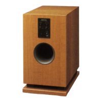
Visual breakdown and part identification for the speaker section.

Schematic Diagrams and Board Layouts

Schematic Diagram U01 Main PC Board

Detailed schematic for the main PC board (NAAF-8829).

Schematic Diagram U02 Frequency Adjustment PC Board

Schematic for the frequency adjustment PC board (NAAF-8830).

Schematic Diagram U04 Voltage Selector PC Board

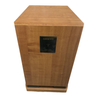
Schematic for the voltage selector PC board (NASW-8832).

Schematic Diagram U03 Power Transformer PC Board

Schematic for the power transformer PC board (NAPS-8831).

Schematic Diagram U05 Power Switch PC Board

Schematic for the power switch PC board (NASW-8833).

Printed Circuit Board Views-1 U01 Main PC Board

Component side layout for the main PC board (NAAF-8829).

Printed Circuit Board Views-2 U03 Power Transformer PC Board

Component side layout for the power transformer PC board (NAPS-8831).

Printed Circuit Board Views-3 U02 Frequency Adjustment PC Board

Component side layout for the frequency adjustment PC board (NAAF-8830).

Printed Circuit Board Views-3 U04 Voltage Selector PC Board

Component side layout for the voltage selector PC board (NASW-8832).

Printed Circuit Board Views-3 U05 Power Switch PC Board

Component side layout for the power switch PC board (NASW-8833).

Service Procedures

Adjustment of Idling Current

Procedure for adjusting the idling current of the amplifier section.

Packing Procedure

Instructions for properly packing the powered subwoofer for shipping or storage.

Related product manuals