EasyManua.ls Logo

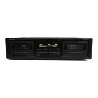
Onkyo TA-RW111

Onkyo TA-RW111
15 pages
To Next Page IconTo Next Page
To Previous Page IconTo Previous Page
Loading...
Remarks
H:Normal
speed
L:
Double
speed
LINE
M
..
s
FS.
i)
1
1
2
3
5
H
H
H
Clock
output
Serial
transfer
data
output
terminals
with
Doably
IC
OI
19
5
(BE
>
Aw
SFR
ERLE
=
‘e)
Z
&
er
|g
=
g
&
(o)
=
2
EF
fg
o
7
0
5
S
S
ao
3
$
a
Data
output
2
.
RESET
System
resetterminal
IL
OSC1
Clock
input/output
terminal
to
internal
oscillator
OSC2
Connect
the
4
MHz
ceramic
resonator.
ND
Clock
input/output
terminals
for
resonator
for
timer
Not
used
Vss
Power
source
terminal
for
A/D
converter
Connect
the
ground.
N
5
w
[A
<
[>
310
|o [<
[&
[A
>
|x
[x
19
SB
2
Bo
|
ls
(s/f
6
IE
Ie |e
3
-j
=
|
w
fa
f=
4
q
5
tH
T1
R.
SENSOR
_
{Signal
input
terminal
from
rotation
sensor
T2R.
SENSOR
20
21
22
23
24
25
26
27
28
29
30
SEARCH
ON/OFF
Initializing’
terminal
of
skip
operation
L
ch
LEVEL
A/D
input
terminal
for
level
input
R
ch
LEVEL
‘Use
the
skip
and
indicator
of
level
meter
Operation
key
connection
terminals
UME
A/D
input
terminal
for
volume
position
detection
Transfer
terminal
with
input
extended
microprocessor
p
Clock
output
WER
OFF
Power
stoppage
detection
input
terminal
System
code
input
terminal
Power
source
terminal
for
A/D
converter
Lo)
32
RI
OUT
System
code
output
terminal
H
Wo
Oo
Q
34
35
36
37
38
39
RECIPB
THT
.
Dolby
mode
selection
terminal
Refer
table
|
NORMAL
Playback
equalizer
and
bias
selector
terminal
HIGH
Refer
table
2.
..
[8
&
|b
mm
|<
ailg
O)
fe
q
41
42
43
4
>
G
oo
<
7
es)
7]
H
44~47
\Grid
4~Grid
[Grid
ouputterminals,
48~63
H
Pull-down
resistor
connection
terminals
UB
MICROPROCESSOR
Connect
the
2
MHz
ceramic
resonator
1
<
a
PACK
|
ag
|
SW
___|Recording
prevention
detection
switch
inp
C
p15
[16
_[raRREcINHsW
[Recording
prevention
detection
switch
input
of
reverse
direction
pom
Inc
:
5
md
Z
al
>
Z
|=
of
forward
direction
-
:
Z
e
2
DOLBY
OFF
DOLBY
OFF
DOLBY
B
DOLBY
C
Table
2

Related product manuals