Do you have a question about the Onkyo TA-2200 and is the answer not in the manual?
Details on tape format, speed, wow/flutter, motors, heads, and power details.
Frequency response, S/N ratio, and input/output characteristics.
Specifications for the RC-146T remote control transmitter.
Instructions for safely replacing the power supply cord.
Procedure for measuring insulating resistance.
Explains recording frequency response with bias.
Describes the fundamental operation of the HX PRO circuit.
Details the conditions under which HX PRO operates.
Block diagram for the Playback Amplifier IC.
Block diagram for the Dolby Noise Reduction IC.
Block diagram for the Meter Drive IC.
Block diagram for the Motor Drive IC.
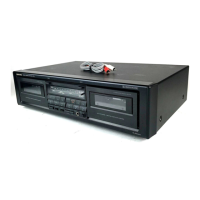
Visual representation of the product packaging.
List of parts included in the product packaging.
Explains the operation of the Full Repeat function.
Details the Block Repeat function and its parameters.
Describes the Auto Music Cassette Selection function.
Essential precautions before performing adjustments.
Lists items, connections, tests, and adjustment points.
Setup for using an oscilloscope for measurements.
Diagrams illustrating test connections and phase relationships.
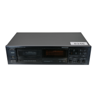
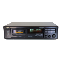
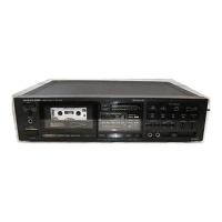
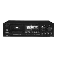
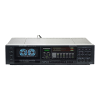
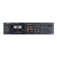
The Onkyo TA-2200 is a stereo cassette tape deck designed for high-fidelity audio recording and playback. This manual provides comprehensive details on its operation, maintenance, and internal components, ensuring users can maximize its performance and longevity.
The TA-2200 is a 4-track, 2-channel stereo cassette deck featuring an AC erase system and a tape speed of 4.8 cm/sec (1-7/8 i.p.s.). Its core functionality revolves around recording and playing back audio on standard cassette tapes. A key feature is the HX PRO circuit, which enhances recording frequency characteristics and bias control. This circuit, utilizing the µPC1297CA IC, dynamically adjusts the recording bias current to maintain optimal frequency response, particularly in the high-frequency range. When the recording signal's time constant (frequency) and level exceed certain thresholds, the VCA (Voltage Controlled Amplifier) reduces the bias current, thereby boosting the high-frequency region. This intelligent bias control ensures that the audio signal is processed instantaneously, resulting in superior recording quality.
The deck incorporates Dolby B and Dolby C Noise Reduction systems, significantly improving the signal-to-noise ratio. Dolby B provides a noise reduction of 10dB above 5kHz and 5dB at 1kHz, while Dolby C offers a more substantial 20dB reduction at 5kHz. These systems are crucial for minimizing tape hiss and other unwanted noise, delivering cleaner and more dynamic audio.
For user interaction, the TA-2200 includes a microcomputer (HD-614048SJ49) that manages various functions. This microcomputer handles inputs from keys such as FF, REW, PAUSE, REC, PLAY, AMCS, AUTO SPACE, STOP, and COUNTER RESET. It also controls outputs for FL tube displays (REC FL, PLAY FL, PAUSE FL, HIGH FL, NORMAL FL, METAL FL, GRID, and SEGMENT displays), line muting, record muting, record/playback selection, bias oscillator control, reel motor rotation (FF and REW directions), solenoid triggering, and capstan motor ON/OFF.
The deck features multiple input and output options, including Line IN, Line OUT, and a Headphone jack. The input sensitivity for Line IN is 60mV with an impedance of 50kohms. Line OUT provides a standard output level of 500mV (0dB) with an optimum load impedance of over 50kohms. The Headphone jack is designed for an optimum load impedance of 8 to 200 ohms.
The TA-2200 offers several advanced playback and recording features to enhance the user experience.
AMCS (Automatic Music Control System): This feature facilitates music selection by putting the mechanism into CUE condition. It monitors signals entering the SEARCH SIGNAL terminal to detect the start of music. Once detected, it plays the music for approximately ten seconds, with the PLAY display flashing at 1Hz. After ten seconds, the machine moves to the next music selection. The system detects gaps between music pieces by converting to normal play time, considering a nominal 5 seconds or actual 2.5 seconds or more as a non-recorded gap.
Remote Control: The TA-2200 supports remote control functionality with the RC-146T Remote Control Transmitter (for U.S.A. and Canadian models only). This infrared transmitter has a signal range of approximately 5 meters (16 feet) and is powered by two AAA batteries, offering convenient control over the deck's operations from a distance.
Display Tube: The BG-654G display tube provides visual feedback on various operational parameters, including counter readings, Dolby NR status, operation mode, tape selector (METAL, HIGH, NORM), and peak level meters for both left and right channels. This comprehensive display keeps the user informed about the deck's status.
The manual emphasizes several crucial maintenance procedures to ensure the TA-2200's optimal performance and safety.
Safety-Related Component Warning: Components marked with a specific symbol on the schematic diagram and in the parts list are critical for fire and electric shock risk. It is imperative to replace these components only with genuine Onkyo parts whose part numbers are specified in the manual. Additionally, leakage-current or resistance measurements must be performed to confirm that exposed parts are adequately insulated from the supply circuit before returning the appliance to the customer.
Power Supply Cord Replacement: The manual details the correct insertion direction for power supply cords into the strain relief. For AS-UC-3 (UD<120V> model), the cord should be inserted lengthwise, while other types of cords should be inserted horizontally to ensure safety.
Insulating Resistance Measurement: To verify electrical safety, the insulating resistance between the power supply cord plug and the chassis must be measured using an insulating-resistance tester. The specification requires more than 10MΩ at 500V.
Adjustment Procedures: Before performing any adjustments, it is critical to clean specific parts with an alcohol-moistened swab. These parts include the record/playback head, pinch roller, erase head, and capstan. It is also essential to demagnetize the record/playback head using a head demagnetizer and to avoid using magnetized screwdrivers for adjustments.
The manual outlines detailed adjustment procedures for various parameters:
These detailed instructions ensure that the TA-2200 can be precisely calibrated and maintained to deliver consistent, high-quality audio performance throughout its lifespan.
| Number of Heads | 2 |
|---|---|
| Track System | 4-track, 2-channel stereo |
| Tape Speed | 4.8 cm/s |
| Motor | DC servo motor |
| Noise Reduction | Dolby B |
| Type | Stereo Tape Deck |
| Tape Type | Type I, CrO2, Metal |
| Wow and Flutter | 0.05% (WRMS) |