HOBO 4-Channel Analog Data Logger (UX120-006M) Manual
Switched 2.5 V Output
The external input channels have a switched 2.5 V output. This
signal can be used to power a sensor directly or to trigger an
external circuit. External sensors should draw no more than 4
mA total when powered.
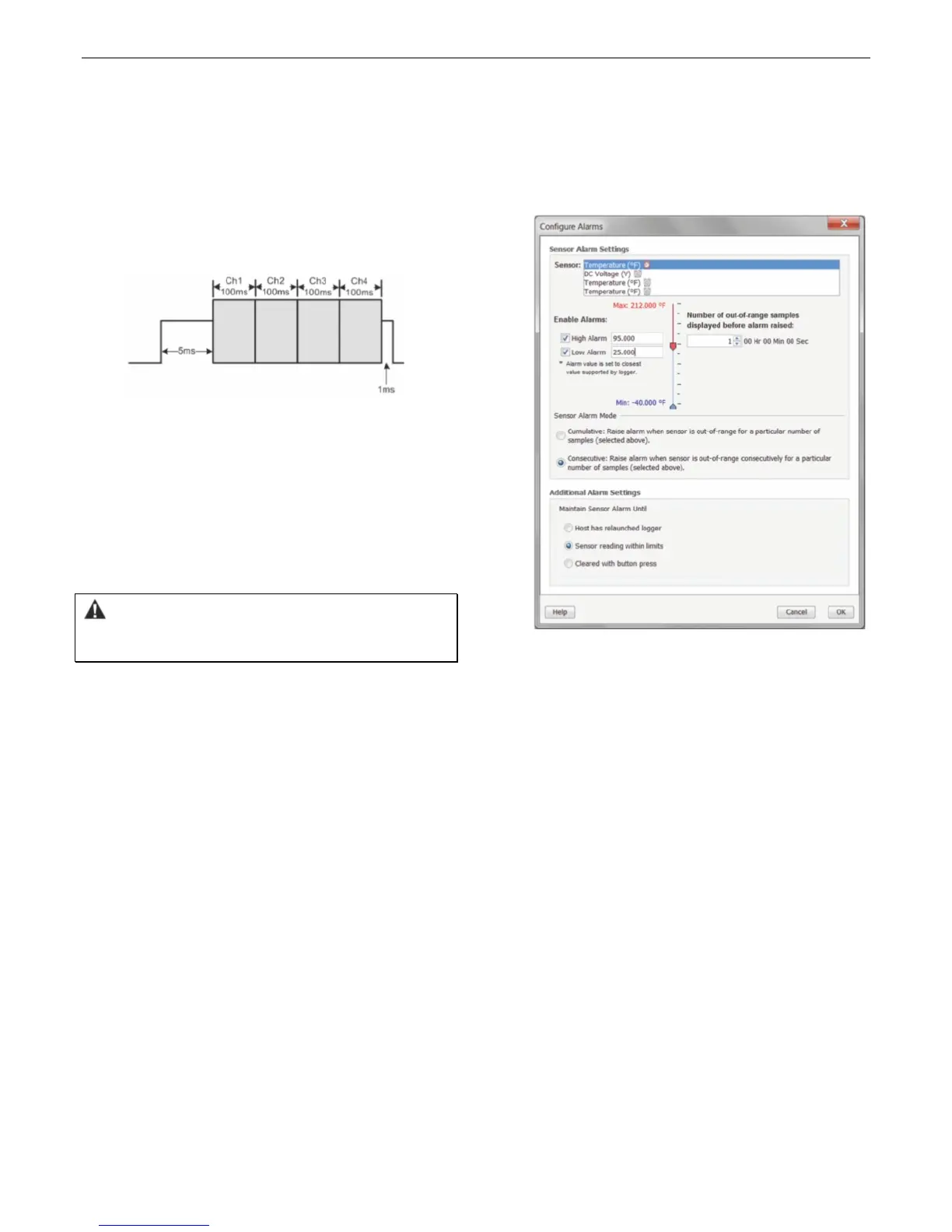
The switched 2.5 V output turns on about 5 ms before the
external channels are measured as shown in the following
diagram. The shaded area shows the 100 ms period for each
enabled channel during which the logger samples the input
signals.
When using multiple voltage and/or current inputs, the (-) from
the current source(s) and the 0 V line from the voltage
source(s) are tied together at the logger. If these lines are at
different voltage potentials, this may cause inaccurate readings
or even damage your logger. Keep in mind that these lines may
also be tied to earth ground through the USB cable when the
logger is connected to the computer. Special precautions may
be necessary if any of the voltage or current source common
lines are not tied to earth ground. Input isolators may be
needed in industrial environments to prevent errors caused by
ground loops.
WARNING: Analog channel input cannot exceed 2.5 V DC.
For sensor outputs up to 24 V DC, use the appropriate voltage
adapter cable (CABLE-ADAPX).
Setting up Alarms
You can set an alarm to trip when a sensor reading rises above
or falls below a specified value on any of the four sensor
channels. To set an alarm:
1. Click the Alarms button from the Launch Logger window. If
the Alarms button is disabled, make sure the Logging Mode
is not set to Burst. (Alarms can only be configured if the
logger is in Normal or Statistics mode.)
2. In the Configure Alarms window, select a sensor from the
list. In the example in this section, a temperature sensor
was selected.
3. Select the High Alarm checkbox if you want an alarm to trip
when the sensor reading rises above the high alarm value.
Type the reading next to the High Alarm checkbox or drag
the red upper slider in the Configure Alarms window.
4. Select the Low Alarm checkbox if you want an alarm to trip
when the sensor reading falls below the low alarm value.
Type the reading next to the Low Alarm checkbox or drag
the blue lower slider.
5. Set the “Number of out-of-range samples displayed before
alarm is raised,” which is the number of sensor readings
needed to trigger each alarm. The time next to the “Number
of out-of-range…” field indicates the amount of time it will
take for the alarm to trip based on the number you entered
in that field and the 15-second LCD refresh rate.
6. Select either Cumulative or Consecutive for the Sensor
Alarm Mode. If you select Cumulative, the alarm will trip
after a specific number of samples (as set in the previous
step) are outside the limits (the high or low samples do not
need to be consecutive). If you select Consecutive, the
alarm will trip after a specific number of samples (as set in
the previous step) outside the limits are displayed in a row.
7. Repeat steps 2 through 6 for any additional sensors.
8. Choose how long the logger should maintain the sensor
alarm once it has tripped. Select “Host has relaunched
logger” if you want the alarm to remain visible on the LCD
until the next time you relaunch the logger. Select “Sensor
reading within limits” if you want the alarm to clear once
the sensor reading returns to the normal range between
the high and low alarm limits. Select “Cleared with button
press” if you want the alarm to remain on until you press
the Alarm/Stats button on the logger.
9. Click OK to save alarm settings.
Notes:
Once the logger is launched, alarms will trip as
determined by these settings. Logger alarms will display
on the LCD screen. Note that the alarm limits are only
checked when the logger’s LCD screen refreshes every 15
seconds.
The actual values for the high and low alarm limits are set
to the closest values supported by the logger based on
the sensor type. This means the value that triggers the
alarm may differ slightly than the value entered.
When you read out the logger, high and low alarm levels
will be displayed on the plot along with “Chan <#> Alarm
Tripped” and “Chan <#> Alarm Cleared” events showing
when the alarm tripped and cleared. The “Chan <#>
Alarm Cleared” event contains the value that was
furthest out of range for the sensor before the alarm
cleared (see the Points table for the actual value).
 Loading...