ENGINE MECHANICAL AND MOUNTS
6A- 15
New inlet valves must not be refaced or lapped with
grinding compound. The correct angle for the intake
and exhaust valve head is 44 degrees.
10. Install cylinder head.
11. Adjust valve clearance. See MAINTENANCE
AND ADJUSTMENTS.
7. Inspect valve guides. Worn or pitted guides can be
reamed to accept valves with oversize stems. Over-
size valves are occasionally used in production.
Oversize valves are marked
’
1
u
“2” or “A” and are
stamped into the valve stem end and also stamped
near spark plug hole. See Figure 6A-22.
Replacing Rocker Arm Studs
1. When replacing rocker arm studs become
neces-
sary,
remove air cleaner, rocker arm cover and
rocker arm.
8. Reseat valve seats in cylinder head in the following
sequence:
Intake
NOTE:
The rocker arm studs are screwed into the
cylinder head. A tapered part of the stem serves to
a void stud loosening.
With 45 degrees cutter, remove burnt structure until
a metallic bright seat is obtained. Lightly coat valve
head with red lead, insert it into guide and turn it
under light pressure several times back and forth.
Thereby a contact pattern is obtained and the seat
width can be measured. If valve does not seat per-
fectly all around, lightly recut valve seat to the estab-
lished seat width of
,049”
-
.059”
with 30 degrees
correction cutter.
Exhaust
The directions for reconditioning intake valve seats
apply in principle also to exhaust valve seat recondi-
tioning with the exception that the valve seat width
should be
.063-,073
in. and different cutters are em-
ployed.
NOTE:
:
OTse
new
valve
seals
whenever
valves are reconditioned.
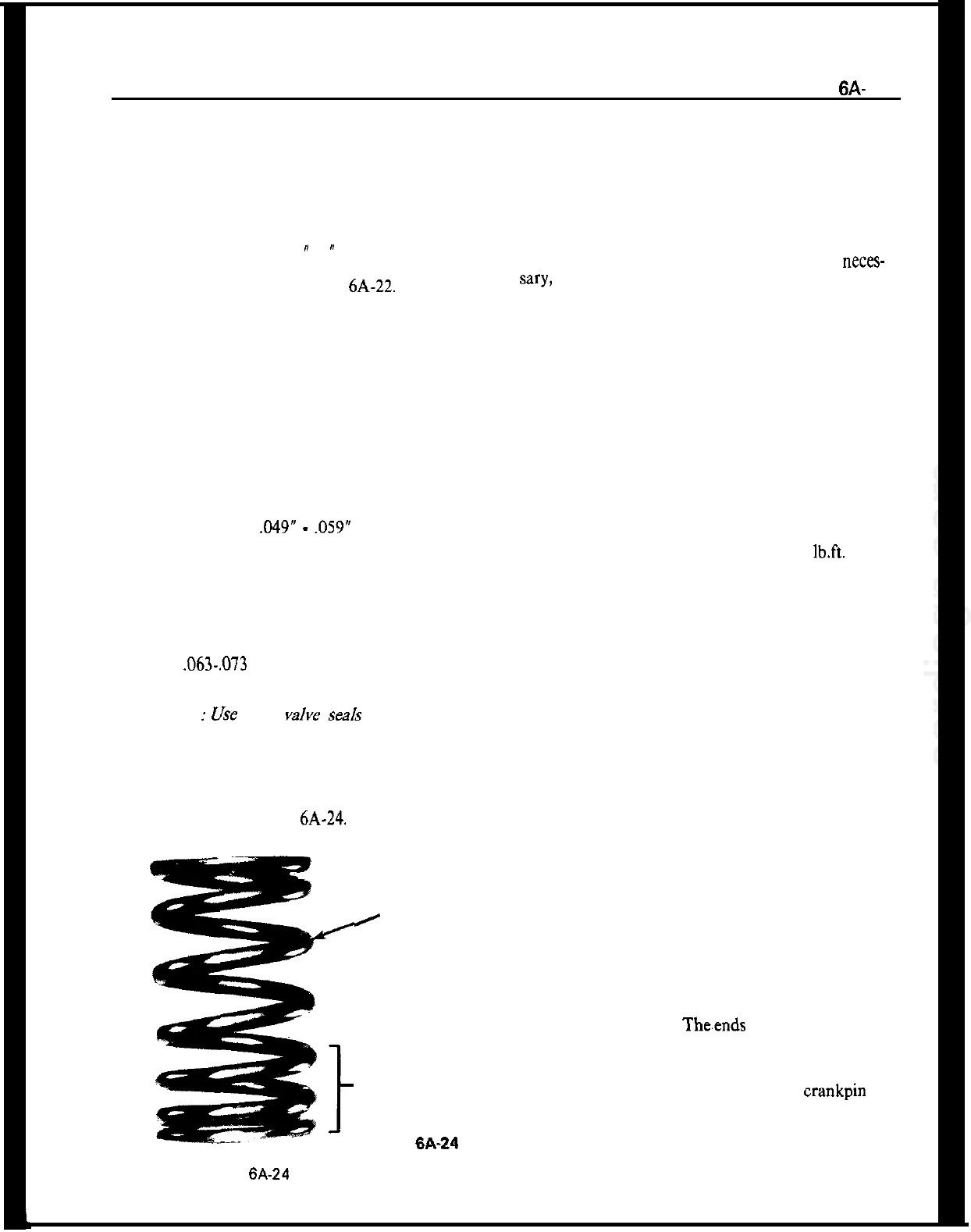
9. Lube valves with engine oil and reinstall valves,
valve springs, caps and cap retainers using J-8062.
Install valve spring with closely wound coils toward
cylinder head. See Figure
6A-24.
2. Attach vise grip pliers to stud being removed and
remove from cylinder head.
3. Screw in new stud. Seat tapered part of stud by
striking stud end with a rubber hammer.
4. Place two turned down rocker arm nuts on
threaded part of stud.
5. Torque stud into cylinder head to 29
lb.ft.
Valve Lifter Service
The valve lifters can be removed after removing
rocker arm cover and rocker arms.
No oversize lifters have been released due to the
insignificant wear of the valve lifters and cylinder
head guides.
Amply oil respective parts and install in reverse se-
quence to removal.
Carry out hydraulic valve lifter adjustment as ou-
tlined in MAINTENANCE AND ADJUST-
MENTS.
VALVE
I
SPRING
CLOSE
WOUND
COILS
TOWARD
HEAD
6A-24
Figure 6A-24 Valve Spring
CONNECTING ROD BEARINGS
A connecting rod bearing consists of two halves or
shells which are alike and interchangeable in rod and
cap. When the shells are placed in rod and cap the
ends extend slightly beyond the parting surfaces so
that when rod bolts are tightened the shells will be
clamped tightly in place to insure positive seating
and to prevent turning. Theends of shells must never
be tiled flush with parting surface of rod or cap.
If a precision type connecting rod bearing becomes
noisy or is worn so that clearance on crankpin is
excessive, a new bearing of proper size must be se-
lected and installed since no provision is made for
adjustment. Under no circumstances should the con-
necting rod or cap be filed to adjust the bearing
clearance.