6A- 16 1973 OPEL SERVICE MANUAL
Inspection of Connecting Rod Bearings and
Crankshaft Journals
Remove oil pan.
After removal of oil pan, disconnect two connecting
rods at a time from crankshaft and inspect the bear-
ings and crankpin journals. While,tuming crankshaft
it is necessary to
t&porarily
reconnect the rods to
crankshaft to avoid possibility of damaging the jour-
nals through contact with loose rods.
If connecting rod bearings are chipped or scored they
should be replaced. If bearings
are
in good physical
condition check for proper clearance on crankpins as
described under, checking clear$nce and selecting
replacement connecting rod beartngs.
If crankpin journals are scored or ridged, the crank-
shaft must be replaced, or reground for undersize
bearings, to insure satisfactory life of connecting rod
bearings. Slight roughness may be polished out with
fine grit polishing cloth thoroughly wetted with en-
gine oil. Burrs may be honed off with a fine oil stone.
Use an outside micrometer to check crankpins for
out- of-round. If crankpins are mpre than
,002”
out-
of- round, satisfactory life of new ,bearings cannot be
expected.
Checking Clearance and Selecting Replacement
Connecting Rod Bearings
Service bearings are furnished in standard size and
several undersizes. The clearance of connecting rod
(and crankshaft) bearings may be checked by use of
Plastigage, Type PG-1 (green), or equivalent, which
is soluble in oil.
1. Remove connecting rod cap with bearing shell.
Wipe off oil from bearing and crankpin journal, also
blow oil out of hole in crankshaft.
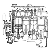
2. Place a piece of the plastic-type gauge material
Figure 6A-25 Checking Bearing
Cleatance
With
Plastic-Type Gauge
lengthwise along the bottom center of the lower bear-
ing shell (Figure 6A-25, view A), then install cap
with shell and tighten nuts to 36 lb. ft. Do not turn
crankshaft with gauge type material in bearing.
3. Remove bearing cap with bearing shell, the flat-
tened piece of gauge will be found adhering to either
the bearing shell or the crankpin. Do not remove it.
4. Using the scale printed on the envelope, measure
the flattened piece of gauge at its widest point. The
number within the graduation which closely corre-
sponds to the width of the gauge, indicates the bear-
ing clearance in thousandths of an inch. See Figure
6A-25, View B.
5. The desired clearance with a new bearing is
.0006”- .0025”. If bearing has been in service it is
advisable to install a new bearing if the clearance
exceeds .003”, however if bearing is in good condi-
tion and is not being checked because of bearing
noise, it is not necessary to replace the bearing.
6. After the proper size bearing has been selected,
clean off the gauge, oil thoroughly, reinstall cap with
bearing shell and tighten nuts to 36 lb. ft.
CRANKSHAFT BEARINGS AND SEALS
Replacement of Crankshaft Bearings
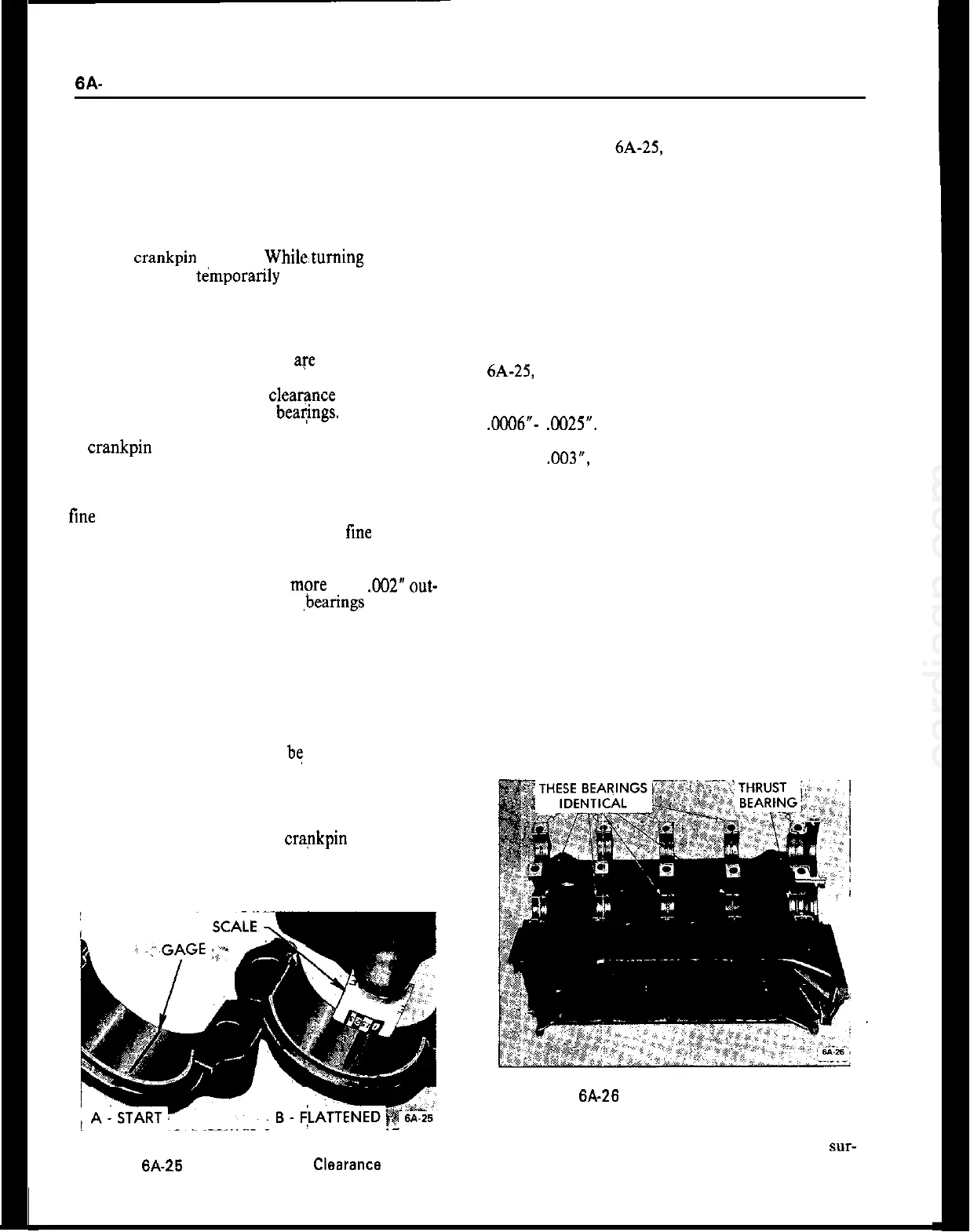
A crankshaft bearing consists of two halves or shells
which are identical and are interchangeable in cap
and crankcase. All crankshaft bearings except the
rear main bearing are identical. The crankshaft end
thrust is taken up the rear (No. 5) main bearing.
Figure 6A-26 Engine Crankshaft Bearings
When the shells are placed in crankcase and bearing
cap, the ends extend slightly beyond the parting
sur-
faces so that when cap bolts are tightened the shells
will be clamped tightly in place to insure positive