ENGINE MECHANICAL AND MOUNTS
6A- 17
seating and to prevent turning.
The
ends of
she//s
must never be tiled flush with parting surface of
crankcase
or
bearing cap.
Crankshaft bearings are the precision type which do
not require reaming to size. Shims are not provided
for adjustment since worn bearings are readily re-
placed with new bearings of proper size. Bearings for
service replacement are furnished in standard size
and undersizes.
Under no circumstances should
crankshaft bearing caps be tiIed to adjust for wear in
old
bearing.
After removal of oil pan, pipe and screen assembly,
perform the following removal, inspection and in-
stallation operations on each crankshaft bearing in
turn so that the crankshaft will be well supported by
the other bearings.
If crankshaft has been removed to check straightness
the following procedure is suggested. Rest crank-
shaft on “V-blocks” at number one and number live
main bearing journals. Check indicator runout at
No. 3 main bearing journal. Total indicator reading
should not exceed
.C012”.
1. Since any service condition which affects the
crankshaft bearings may also affect the connecting
rod bearings, it is advisable to inspect connecting rod
bearings
first.
If crankpins are worn to the extent
that crankshaft should be replaced or reground, re-
placement of crankshaft bearings only will not be
satisfactory.
If replacement of cylinder block or crankshaft is re-
quired, always check main bearing clearance with
plastic-type gauge to obtain specified limits.
2. Remove one bearing cap, then clean and inspect
lower bearing shell and the crankshaft journal. If
journal surface is scored or ridged, the crankshaft
must be replaced or reground to insure satisfactory
operation with new bearings. Slight roughness may
be polished out with tine grit polishing cloth
thoroughly wetted with engine oil, and burrs may be
honed off with a tine stone.
3. If condition of lower bearing shell and crankshaft
journal is satisfactory, check the bearing clearance
with a plastic-type gauge.
4. When checking a crankshaft bearing with plastic-
type gauging material, turn crankshaft so that oil
hole is up to avoid dripping of oil on the gauge
material. Place paper shims in lower halves of adja-
cent bearings and tighten cap bolts to take the weight
of crankshaft
off
the lower shell of beating being
checked.
5. If bearing clearance exceeds
.C03”,
it is advisable
to install a new bearing; however, if bearing is in
good condition and is not being checked because of
bearing noise, it is not necessary to replace the bear-
ing.
6. Loosen all crankshaft bearing cap bolts
l/2
turn,
and remove cap of bearing to be replaced.
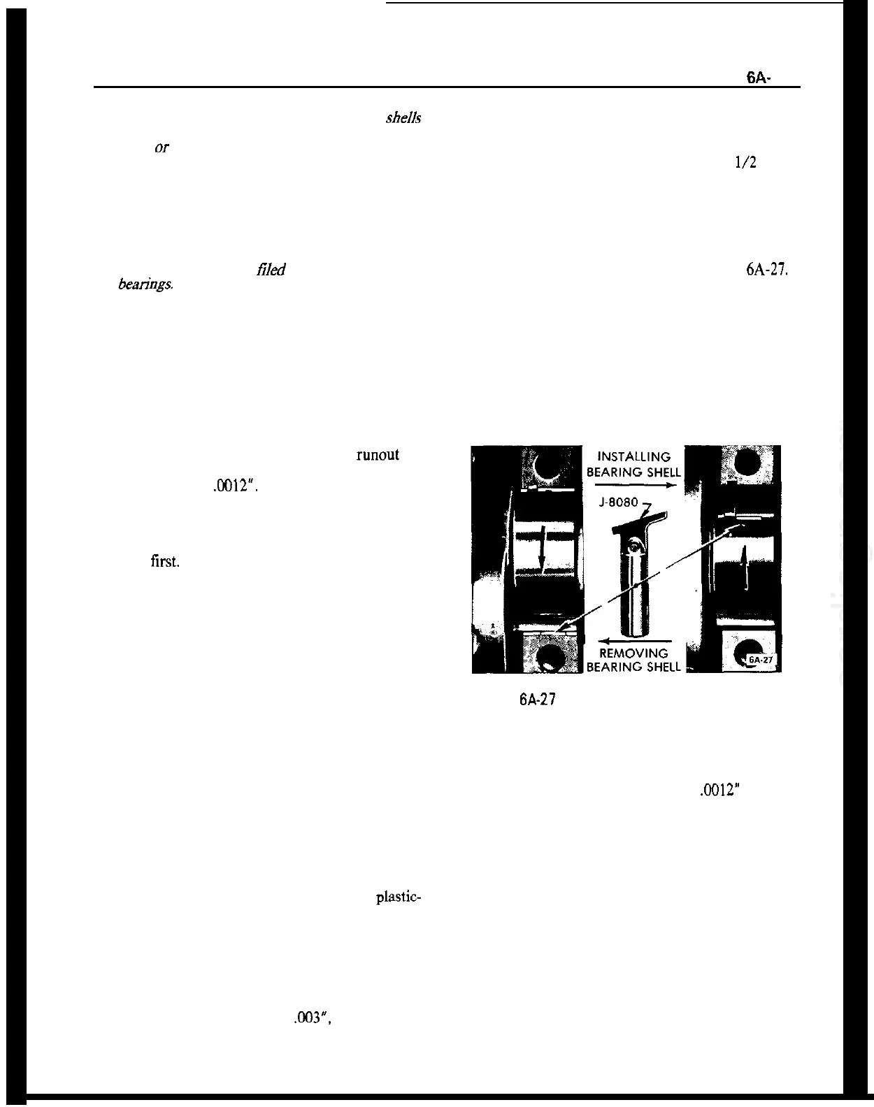
7. Remove upper bearing shell by inserting Bearing
Shell Remover and Installer J-8080 in oil hole in
crankshaft, then slowly turning crankshaft so that
the tool rotates the shell out of place by pushing
against the end without the tang. See Figure
6A-27.
When turning crankshaft with rear bearing cap
removed hold oil seal to prevent it from rotating out
of position in crankcase.
8. The crankshaft journal cannot be measured with
an outside micrometer when shaft is in place; how-
ever, when upper bearing shell is removed the jour-
nal may be checked for out-of-round by using a
special crankshaft caliper and inside micrometer.
Figure 6A-27 Removing and Installing Crankshaft
Bearing Upper Shell
The caliper should not be applied to journal in line
with oil hole.
If crankshaft journal is more than
.M)12”
out-of-
round, the crankshaft should be replaced since the
full mileage cannot be expected from bearings used
with an excessively out-of-round crankshaft.
9. Before installation of bearing shells make sure that
crankshaft journal and the bearing seats in crankcase
and cap are thoroughly cleaned.
10. Coat inside surface of upper bearing shell with
engine oil and place shell against crankshaft journal
so that tang on shell will engage notch in crankcase
when shell is rotated into place.
11. Rotate bearing shell into place as far as possible
by hand, then insert Installer J-8080 in crankshaft oil
hole and rotate crankshaft to push shell into place.
Bearing shell should move into place with very little