6A- 22 1973 OPEL SERVICE MANUAL
I.
NO.
I
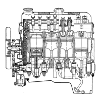
COMPRESSION - GAP IN FRONT
2. NO. 2 COMPRESSION - GAP IN REAR
3. UPPER STEEL BAND -
I
-
2
IN.TOWARDS
THE LEFT OF INTERMEDIATE RING GAP
4. INTERMEDIATE RING - GAP IN FRONT
5. LOWER STEEL BAND -
I
- 2 IN.TOWARDS
THE RIGHT OF INTERMEDIATE RING GAP.
‘A” VERTICAL LINE FOR PISTON AND RINGS, FRONT
6A-36
Figure 6A-36 Location of Piston Ring Gaps
With rings installed on piston, check clearance in
grooves by inserting feeler gages between each ring
and its Iower land. Any wear that occurs forms a
step at inner portion of the lower land. If the piston
grooves have worn to the extent that relatively high
steps exist on the lower lands, the piston should be
replaced since steps will interfere with the operation
of new rings causing ring clearances to become exces-
sive. Piston rings are not furnished in oversize widths
to compensate for ring groove wear.
When fitting new rings to new pistons, the side clear-
ance of the compression rings should be X024”
-
.1X34”
(top) and
.0013”
-
.OO24”
(2nd), and the oil
ring clearance should be
.OO13”
-
.0024”.
Assembly of Piston and Connecting Rod
NOTE:
Connecting rods may be out of alignment
due to shipping or hand/i& Always check a new
rod before installing piston and pin.
Inspect piston pin bores and piston pins for wear.
Piston pin bores and piston pins must be free of
varnish or scuffing when being measured. The piston
pin should be measured with a niicrometer and the
piston pin bore should be measured with a dial bore
gage or an inside micrometer. If clearance is in excess
of the
,001”
wear limit, the piston and piston pin
assembly should be replaced.
1. Lubricate piston pin holes in piston and connect-
ing rod to facilitate installation of pin.
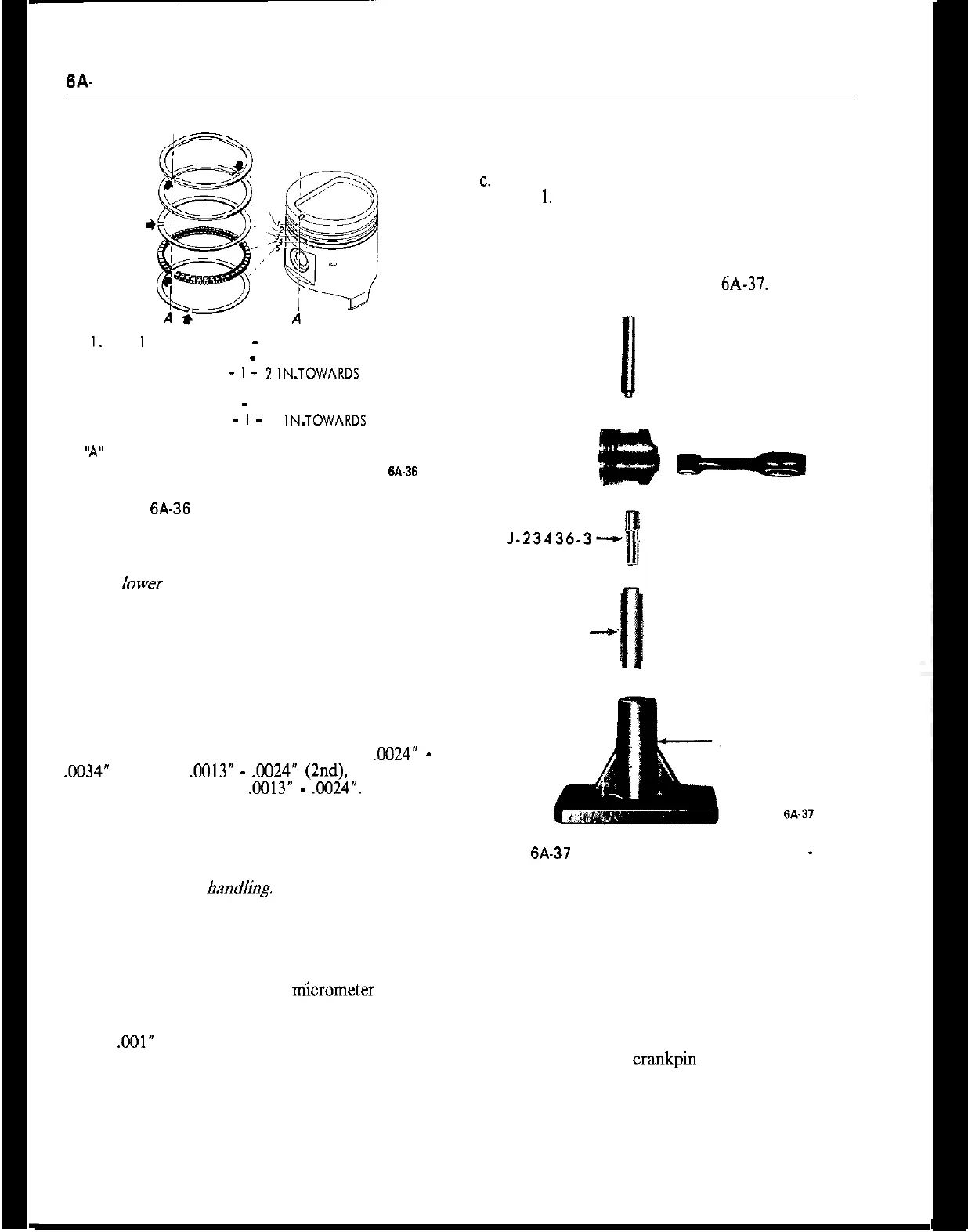
2. Install pin in following manner:
a. Position base support J-6047 on hydraulic press.
b. Place tool J-23436-l in support J-6047 with small
diameter bore facing upward.
c.
Place small end of tool J-23436-3 in bore of tool
J-23436-
1.
d. Position piston, rod, and pin guide J-23436-3.
e. Line up pin on piston, and using tool J-23436-4
press pin into piston. See Figure 6A-37.
Ii
-J-23436-4
J-23436-3--,
J-23436-1
--c
J-6047
Figure 6A-37 Piston Pin Installation Tool Layout
-
1.9
Engine
3. Remove installer from connecting rod and piston
assembly and check piston for freedom of movement
on piston pin.
4. Make sure cylinder bores, pistons, connecting rod
bearings and crankshaft journals are absolutely
clean, then coat all bearing surfaces with engine oil.
5. Before installation of a piston and rod assembly in
its bore, position the crankpin straight down.
6. Remove connecting rod cap.
7. Make sure the gap in the oil ring rails and the gaps
of the compression rings are positioned correctly.
8. Lubricate the piston and rings and install in bore