ENGINE MECHANICAL AND MOUNTS 6A- 23
1.
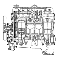
NOTCH IN PISTON HEAD
POINTING TOWARD THE FRONT
2. OIL HOLE IN CONNECTING ROD
POINTING TOWARD THE RIGHT
(MANIFOLD SIDE)
3. NOTCH IN CONNECTING ROD
CAP POINTING TOWARD THE
REAR
6A-36
Figure 6A-39 Piston and Rod Assembly
by oompressing the rings with a “wrap around” com-
pressor.
9. Select a new connecting rod bearing, if necessary.
Otherwise install cap with bearing lower shell on rod
and tighten bolt nuts to 36
lb.ft.
torque.
10. Install all other piston and rod assemblies in same
manner. When piston and rod assemblies are prop
erly installed, the oil spurt holes in the connecting
rods will be facing right.
11. Check end clearance between connecting rods in
each crankpin using feeler gages. Clearance should
be between
.0043”
and .0095”.
12. Install cylinder head. Torque 10 cylinder head
bolts to 72 lb.ft (cold), and 2 cylinder head to timing
chain cover bolts to 17
lb.ft.
13. Install new oil pan gasket by first installing flange
gasket with tabs in slots in rear main bearing cap and
engine front cover. Then install rubber strips in
grooves in rear main bearing cap and engine front
cover. Install oil pan, torquing bolts to 5 lb.ft.
14. Install (Opel
1900
and Manta) front suspension
assembly. (GT) Install engine suspension cross mem-
ber.
After installation of new pistons and rings, care
should be used in starting the engine and in running
it for the first hour. Avoid high speeds until the parts
have had a reasonable amount of break-in so that
scuffling
will not occur.
TIMING CHAIN COVER AND TIMING CHAIN
Timing Chain Cover Removal
1,
Support engine in vehicle as outlined under Engine
Oil Pan Removal and Installation.
2. Remove radiator and shroud assembly
3. Remove cylinder head.
4. Remove alternator belt and remove alternator
mounting bracket.
5. Remove fuel pump
6. Remove ignition distributor.
7. Remove chain tensioner assembly out of timing
cover.
8. Remove crankshaft pulley bolt and remove pulley.
9. Remove water pump assembly.
10. Remove oil pan
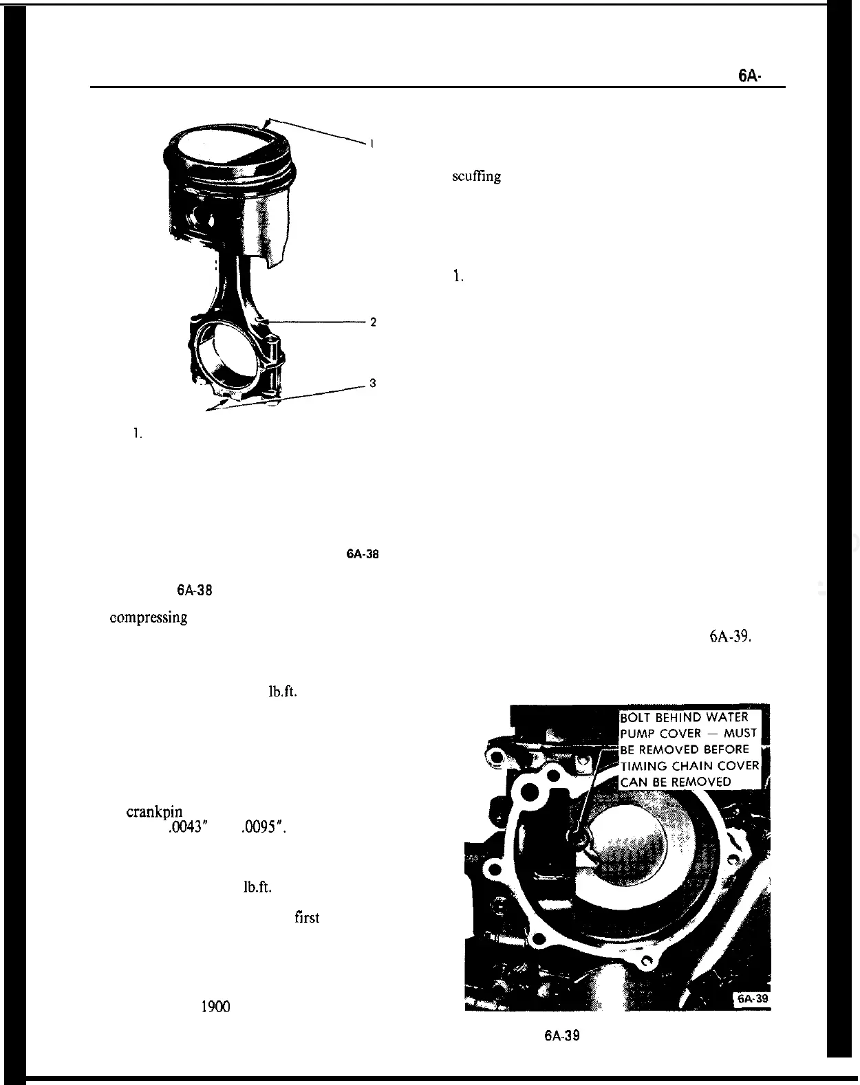
11. Remove timing chain cover bolts. One bolt is
covered by the water pump. See Figure 6A-39.
12. Pull off sprockets with chain. Put a paint mark
Figure 6A-39 Bolt Behind Water Pump