6A- 26 1973 OPEL SERVICE MANUAL
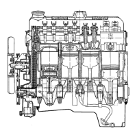
rear of cylinder head. Remove camshaft toward
front, supporting camshaft with one hand through
access hole and taking care not to damage bearing
surfaces. See Figure 6A-43.
1
2
345 6
I.
OLD PRESSURE
4. COVER GASKET
RELIEF
~~-
\SSEMBLY
5. COVER 8 VALVE
ASSEMBLY
VALVE
I
2. TIMING CASE
6. COVER ATTACHING
3. OIL PUMP GEARS
SCREWS
1
2 3
”
4
5
Figure 6A-44 Oil Pump Components
1.
CAMSHAFT
2. FRONT ACCESS HOLE
3. LATERAL ACCESS HOLE
4. CYLINDER HEAD
5. REAR ACCESS HOLE
ISA-43
Figure 6A-43 Removing Camshaft
Installation
1. Liberally lubricate camshaft journals and install
camshaft from front into cylinder head. Support
shaft through access hole in left side of head to pre-
vent damaging bearings.
2. Reinstall valve lifters, rocker arms and self- lock-
ing rocker arm nuts.
3. Install rear and side access plates.
4. Reinstall cylinder head.
OIL PUMP COVER AND GEARS
Removal and Installation of Oil Pump
Cover and Gears
1.
Remove screws attaching oil pump cover assembly
to timing chain cover. Remove cover assembly and
slide out oil pump gears. See Figure 6A-44.
2. Wash off gears and inspect for wear, scoring, etc.
Replace any gears not found serviceable. Discard
pump covers scored by gear action. If pump housing
or distributor drive shaft bushing are worn (this is
only possible after a long service life), the timing case
together with all exchangeable pump parts have to be
discarded.
In isolated cases, timing cases are installed in pro-
duction having
.008
in. oversize bores for pump gears
and shafts. Oversize bores may exist either for one or
both gears; these timing cases are identified by the
number “0.2” stamped into pump flange on left and-
/or right-hand side. Oversize replacement gears
should be selected according to Part Catalog specifi-
cations.
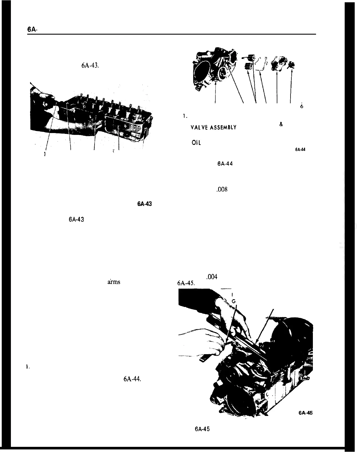
3. Liberally lubricate spindles and gear teeth and use
new cover gasket. Install oil pump cover.
If new gears are installed, their end clearance in a dry
pump housing should be checked with a straight
edge and a feeler gauge. The gears must not protrude
more than X04 in. over pump housing. See Figure
6A-45.
FEELER
AUGE
STRAIGHT
I EDGE
Figure 6A-45 Checking Oil Pump Gear End Clearance