ENGINE MECHANICAL AND MOUNTS
6A- 25
1,
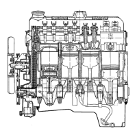
CAMSHAFT SPROCKET
2. CAMSHAFT SPROCKET SUPPORT
3. LONG DAMPER BLOCK
4. CRANKSHAFT SPROCKET
5.
CHAIN AND DAMPER BLOCK
IN PARALLEL
6. CRANKSHAFT KEY
7. PAINT MARK ON FRONT
8.
TIMING CHAIN
9. MARK ON CAMSHAFT
SPROCKET SUPPORT
IO. MARK ON CAMSHAFT
SPROCKET
6A-41
Figure 6A-4 1 Valve Timing Marks
Removal
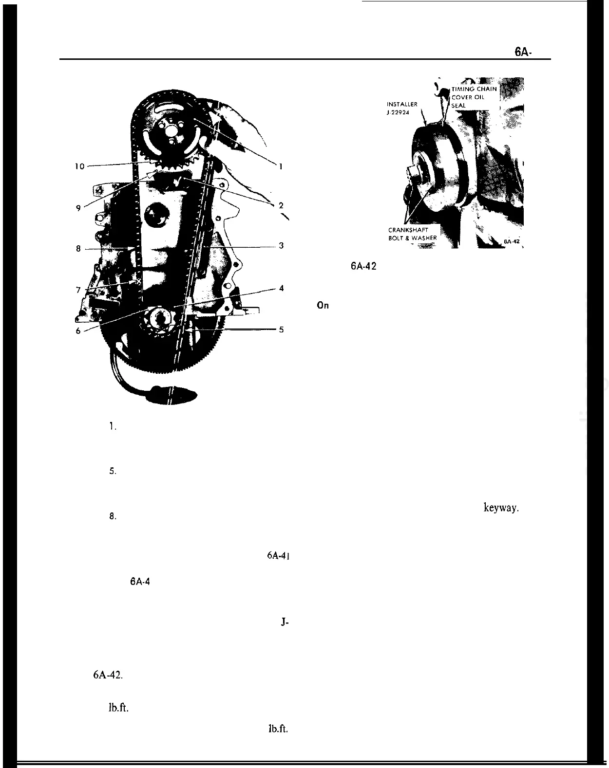
4. Lubricate new oil seal and place on installer
J-
22924.
1. Remove cylinder head.
5. Place installer J-22924 on crankshaft. Using
crankshaft bolt and washer install seal into cover. See
Figure 6A-42.
2. Loosen self-locking rocker arm nuts and swing
rocker arms off valve lifters.
6. Install crankshaft pulley, bolt and washer. Torque
bolt to 72
Ib.ft.
3. Remove valve lifter. Place lifters in a suitable hold-
ing fixture so that they may be reinstalled in original
position.
7. Install belts and torque to proper tension 45
lb.ft.
4. Remove cover from access hole on left side and
Figure 6A-42 Installing Timing Chain Cover Oil Seal
Replacing Distributor Drive Gear
On Crankshaft
1. Remove fan belt.
2. Remove fuel pump. Plug end of fuel line with a
suitable stop.
3. Remove spark plug wires, distributor hold down
clamp. Remove distributor.
4. Turn crankshaft so key is on top.
5. Pry oil seal out of timing chain cover.
6. Insert a screwdriver through opening for fuel
pump and push out distributor drive gear, which has
a push tit on crankshaft, through oil seal seat in
timing cover.
7. Install new gear. Be sure key tits in
keyway.
When
installing components, use new gaskets as required.
8. Install new oil seal.
9. Connect parts removed in steps 1 thru 3.
CAMSHAFT