Instructions:
Step 1: Label wires and remove your existing sprinkler controller.
● Carefully label and remove the wires from your existing sprinkler controller, then remove it from the wall.
Typically you will see the power supply wires, the COM (common) wire, one or more Zone wires. Depending
on your setup, you may also find a Master Zone (or Pump Start Relay) wire, and Rain / Soil / Flow Sensor
wires (if using any such sensor).
Step 2: Attach OpenSprinkler to the wall, and re-insert the wires:
● Refer to the Hardware Interface diagram and Zone Wire Connection diagrams on the previous pages. All
terminal blocks on OpenSprinkler can be unplugged for easy wiring. To unplug, firmly grab both ends of the
terminal block, wiggle, and pull it out.
● Insert COM and zone wires to their corresponding terminal ports on OpenSprinkler.
○ For OpenSprinkler DC and LATCH: OpenSprinkler's COM terminal is positive (+). If your solenoid wires
have polarity, make sure its positive wire (typically red) goes to COM.
● For OpenSprinkler AC, insert and tighten the 24VAC wires into the Orange terminal block (AC has no polarity
so the two wires have no distinction);
For OpenSprinkler DC or LATCH, insert the DC power adapter into the power barrel on OpenSprinkler.
● A sensor should be connected between SN1 and GND (or SN2 and GND if using a second sensor).
Do NOT plug in any sensor wire to COM -- OpenSprinkler uses GND (not COM) as common for sensors. For
additional details on how to connect sensors (e.g. rain or flow sensor), refer to later sections in this manual.
Step 3: Link OpenSprinkler Zone Expanders (Optional):
● To link zone expanders: first, power off the main controller; then plug one end of the zone extension cable
into OpenSprinkler’s Zone Expander Connector: the connector is polarized so you can only plug it in one way.
○ For OpenSprinkler 2.3 or OSPi: plug the other end of the cable to Zone Expander's IN connector. If you
have multiple expanders, daisy chain them by following the OUT → IN links.
○ For OpenSprinkler v3: plug the other end of the cable to either of Zone Expander's connectors on the side.
If you have multiple expanders, use additional cables to link them (again, the two ports on each expander
are identical so you can use either). Because all Zone Expanders are hooked onto the same (I2C) bus, you
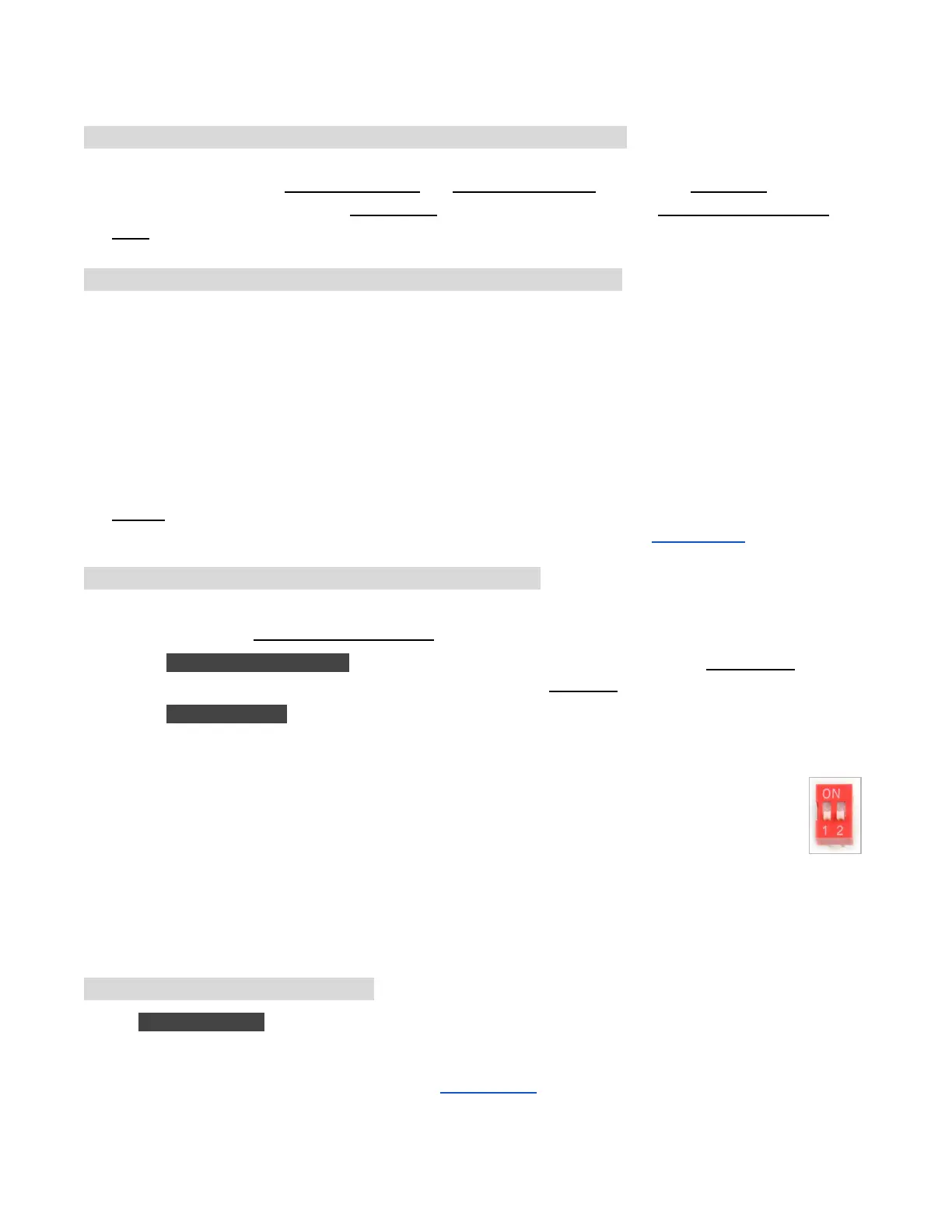
must set for each Zone Expander a unique index (1, 2, 3, or 4). Each Zone Expander has a DIP
switch (see picture on the right) that allows setting the index. The first expander (directly
connected to the main controller) should have an index of 1 (OFF OFF on the DIP switch), the
second expander should be 2 (ON OFF), the next is 3 (OFF ON), and the last is 4 (ON ON).
Zones on the main controller correspond to indices 1 to 8; zones on the first expander (DIP position OFF
OFF) correspond to indices 9 to 24; and so on. The firmware can detect the expander with the highest
index, however, you still need to manually set the number of zones in settings. You can set more zones
than physically available, to take advantage of 'Virtual Zones' features (e.g. Remote, HTTP, RF zones).
Step 4: Setting Up Ethernet or WiFi
● For OpenSprinkler 2.3: plug in a wired Ethernet cable to OpenSprinkler's Ethernet jack, the other end to your
router. If you prefer using WiFi connection, we recommend you to purchase OpenSprinkler v3, which has
built-in WiFi. (If you have an OpenSprinkler 2.3 and want WIFi connection, you can use a powerline Ethernet
adapter, or a pocket-size travel router. Check our Video Tutorial for specific instructions).
OpenSprinkler Firmware 2.1.9 User Manual 5