Electrical Inputs
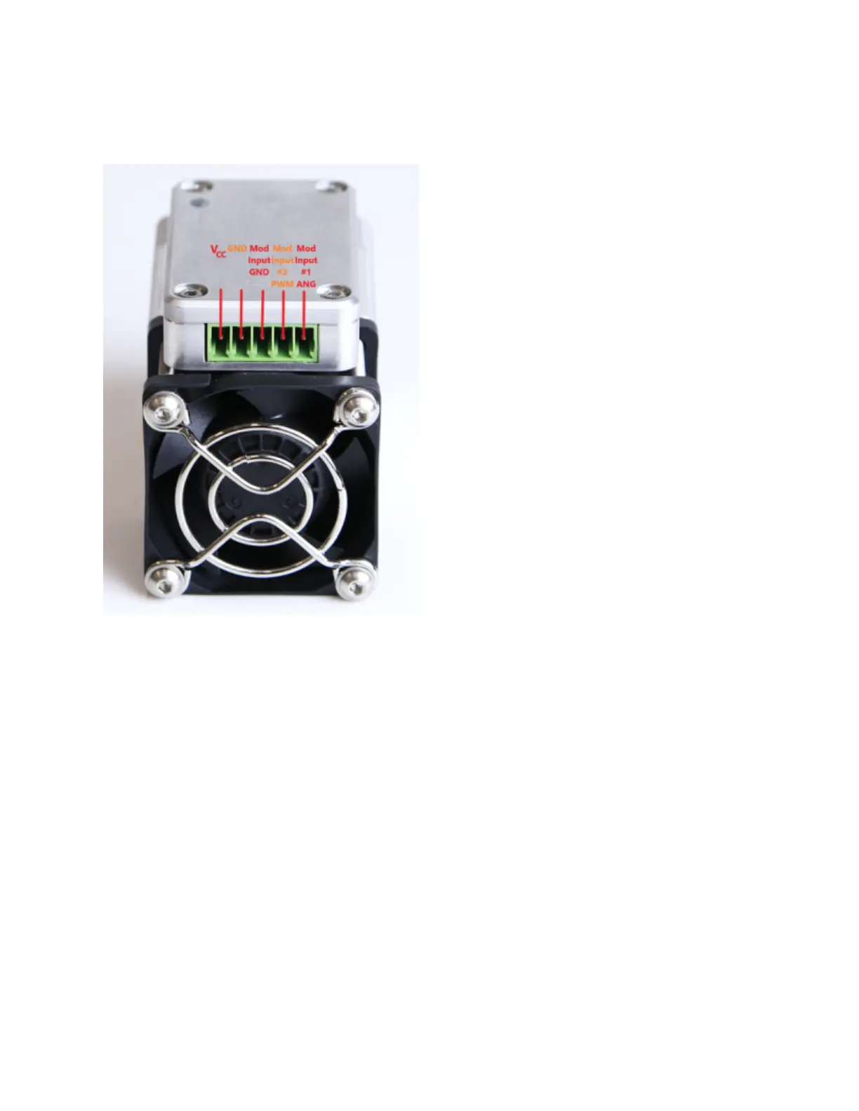
Pin Descriptions:
1. Mod Input #1 ANG
Modulation input #1 accepts analog or Pulse-Width Modulation (PWM) signals. The
operating range of modulation input #1 is 0 - 5 V. If it is connected to a signal with a
slightly higher voltage, e.g. 0 - 10 V, only the 0 - 5 V part of the signal will affect the laser
power. The voltage connected to this input should not exceed 10 V.
NB: Do not connect control signal cables simultaneously to the Mod Input #1 ANG pin
and Mod Input #2 PWM.
NB2: Mod Input #1 ANG and Mod Input #2 PWM pins share a common ground in the
form of pin #3 (Mod Input GND).