600-8815 Kyoto, Shimogyo, Awata Chudoji 91, Japan
TEL : +81-(0)75-325-2920
FAX: +81-(0)75-325-2921
Website : http://www.optex-fa.com
Z3 SERIES
• Z3T-2500 □□ • Z3R-Q200 □□
• Z3R-400 □□ • Z3D-L09 □□
• Z3D-100 □□
INSTRUCTIONMANUAL
●lPleaseconrmifspecicationsfulllyourneeds.
●lPleasereadthismanualcarefullybeforetheuseandkeepthisfor
futurereference.
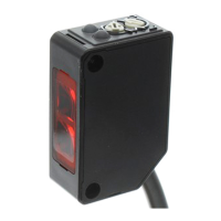
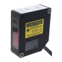
PhotoelectricSensor
DIMENSIONS
Bracketsforinstallationareoptionalandnotincludedinthiskit.
(Notstandardaccessoryandpleasepurchaseifneeded.)
Output indicator(orange)
Stable indicator(green)
Sensitivity adjuster L/ON , D/ON selector
7.3
4.4
16
10
21.2
15.5
7.7
12.4
21.2
Sender
Through beam sender・
Receiver
Retro Coax. Receiver
19
18.8
Optical axis
(Sender,Receiver)
BEF-W100-B
Cable type : When using brackets of BEF-W100-B (option)
φ 3.8 2m Cable
2-M3 P0.5
Output indicator(orange)
Stable indicator(green)
Sensitivity adjuster L/ON , D/ON selector
11
20
25.4
31
11.9
1.2
12.4
Through beam sender・
Receiver
Retro Coax. Receiver
19
18.8
Optical axis
(Sender,Receiver)
BEF-W100-B
Connector type : When using brackets of BEF-W100-A (option)
出力表示灯(橙)
安定表示灯(緑)
感度調整ボリウム
ライトON/ダークON切替スイッチ
2-M3 P0.5
M8 3/4-pin connector
5.812.6
1.7
5.2
32.4
3
13.7
4.4
8.2
14
18.8
19
11
20
25.4
0.7
31
11.9
26
Sender
Through beam sender・
Receiver
Retro coax, receiver
BEF-W100-A
Optical axis
(Sender,Receiver)
Adjusting the potentiometer
①
A
Setthedetectableobjectatthedetectionpositionandturnthepotentiometer
fromMINtowardMAXuntiltheoutputindicator(orange)lightup.Callit
positionA.
②
RemovedetectableobjectandturnthepotentiometerfromMAXtowardMIN
positionwheretheoutputindicator(orange)isextinguished.CallitpositionB.
③
A
B
PointCmidwaybetweenAandBistheoptimumsensitivityposition.The
positionAandBmayreversebytypesanddetectingsituation.
Reflectors(option)
ForRetroReectiveuseonly
Pleaseconrmappropriatetypeconsideringsensingdistanceandconditionstouse.
Reectorsareoptionalandnotincludedinthiskit.
(Notstandardaccessoryandpleasepurchaseifneeded.)
●
StandardType Type:V-61
Sensingdistance:0.01~4m(RetroReectiveType)
●
Smallreector Type:V-42
Sensingdistance:0.01~2.4m(RetroReectiveType)
47
51.6
20
40
61.6
51
475
4.4
8.6
3
35
31
31
35
42
3.65
25 3.5
8
2- n 3.6
●
Smallreector Type:P-45A
Sensingdistance:0.01~1.4m(RetroReectiveType)
2.2
8.4
33.3
45
54
φ7
φ3.5
12.4
6.2
SPECIFICATION
Through Retroref. Diusedref.
Transparentobjects
Limitedrange
Cabletype Z3T-2500(N/P) Z3R-400(N/P) Z3D-100(N/P) Z3R-Q200(N/P) Z3D-L09(N/P)
Connectortype Z3T-2500C(N4/P4) Z3R-400C(N4/P4) Z3D-100C(N4/P4) Z3R-Q200C(N4/P4) Z3D-L09C(N4/P4)
Nominaldistance
*1
25m 0.01~4m 0~1m 0.01~2m 10~90mm
LightSource RedLED
Spotsize φ 1800㎜ /25 m φ 280㎜ /4 m φ 75㎜ /1200㎜ φ 140㎜ /2 m φ 8㎜ /90㎜
Supplyvoltage DC10 ~ 30VIncludingripple(P-P)10%
Currentconsumption
Sender:20mAmax
20mAmax 25mAmax 20mAmax
Receiver:15mAmax.
Responsetime 500µsmax
Controloutput NPN/PNPOpencollector 100mAmax./DC30Vmax.(Residualvoltage1.8Vmax.)
Operationmode LightON,DarkON Selectablebyswitch
Sensitivityadjustment 1turnvolume
Indicator Outputindicator(orangeLED)/Stableindicator(greenLED)
Ambienttemp. / humidity
-25 ~ 55℃ /35 ~ 85%RH (Nocondensationorfreezing)
Storagetemp. / humidity
-40 ~ 70℃ /35 ~ 95%RH (Nocondensationorfreezing)
protectioncategory/material
IP67/Case:ABS,FrontCover:PMMA
*1Sensingdistanceshowedinabovetableistypicalvalueineachtype.
・
Retroref.
/
Transparentobjectstypes
:ReectorV-61(option)
・
Diusedref.type
:Whtieplate200x200mm
・
Limitedrangetype
:Whiteplate100x100mm
INPUT AND OUTPUT CIRCUIT DIAGRAM
NPN type Through beam emitter
Protection
Main circuit
Load
circuit
4
1
1
3
4
3
M8 3pin M8 4pin
Brown
Blue
Blue
Black
Brown
①
DC10
~
30V
③
0V
④
Control output
①
DC10
~
30V
③
0V
Protection
Main circuit
Load
circuit
Main circuit
Blue
Black
Brown
①
DC10
~
30V
③
0V
④
Control output
Protection
Main circuit
Load
circuit
4
1
1
3
4
3
M8 3pin M8 4pin
Brown
Blue
Blue
Black
Brown
①
DC10
~
30V
③
0V
④
Control output
①
DC10
~
30V
③
0V
Protection
Main circuit
Load
circuit
Main circuit
Blue
Black
Brown
①
DC10
~
30V
③
0V
④
Control output
PNP type Connector pin No.
Protection
Main circuit
Load
circuit
4
1
1
3
4
3
M8 3pin M8 4pin
Brown
Blue
Blue
Black
①
DC10
~
30V
③
0V
④
Control output
Protection
Main circuit
Load
circuit
Main circuit
Blue
Black
Brown
①
DC10
~
30V
③
0V
④
Control output
Protection
Main circuit
Load
circuit
4
1
3
M8 3pin M8 4pin
Brown
Blue
Blue
Black
Brown
①
DC10
~
30V
③
0V
④
Control output
①
DC10
~
30V
③
0V
Protection
Main circuit
Load
circuit
Main circuit
Blue
Black
Brown
①
DC10
~
30V
③
0V
④
Control output
①・・・DC10~30V
③・・・0V
④・・・Controloutput
Attachment
•
Tighteningtorqueneedtobeunder0.5N•m.
•
UseM3screwtomount.
Safety Precautions
●Itisdangeroustowireorattach/removetheconnector
withthepoweron.Makesuretoturnothepowerbefore
operation.
●Makesuretousetheproductwiththeprotectivecover
attachedandclosed.
●Installinginthefollowingplacesmayresultinmalfunction:
1.Adustyorsteamyplace
2.Aplacegeneratingcorrosivegas
3.Aplacedirectlyreceivingscatteringwateroroil.
4.Aplacesueredfromheavyvibrationorimpact.
●Theproductisnotdesignedforoutdooruse.
●Donotusethesensorintransientstateafterpoweron
(approx.100ms).
●Donotwirewiththehighvoltagecableorthepowerline.
Failuretodothiswillcausemalfunctionbyinductionor
damage.
●Thesensorperformanceordigitaldisplayvaluesmay
dependontheindividualunitsortheconditionofdetected
product.
●Thisproductisnotanexplosion-proofconstruction.
Donotusetheproductunderammable,explosive
gasorliquidenvironment.
●Donotusetheproductinwater.
●Donotdisassemble,repair,orconverttheproduct.
Failuretodothismaycausefailure,re,orelectricshock.
●Operatewithintheratedrange.
This product cannot be used as a safety device
to protect human body.