Do you have a question about the OPTICLIMATE PRO3 Series and is the answer not in the manual?
Details on how to install the fan on the short side of the unit for narrow rooms or gable roofs.
Specifies required clearance from walls and ceiling for proper air suction and noise reduction.
Instructions for mounting the unit using rubber feet and thread ends for stability.
Guidance on using insulating springs for quieter operation and automatic condensate drainage.
Describes connecting the electric solenoid valve using the provided black cable.
Details connecting the water leakage sensor to stop water supply upon detection.
Explains the alarm port for connecting to external alarm or GSM detectors.
Information on the automatic moisture meter with a light cell for day/night mode switching.
Guidance on positioning the room temperature sensor for accurate readings.
Instructions for hanging and connecting the remote control for external operation.
Specifications for power cables and circuit breakers based on OptiClimate models.
Specific wiring instructions for inverter models (1-phase 230V and 3-phase 400V).
Using a timer to switch off heat sources when room temperature becomes too high.
Details on water inlet/outlet, solenoid valve placement, and pipe insulation.
Instructions for connecting the condensation drain, including lift pump usage.
Explanation of the remote control buttons and their operations.
How to turn the unit on/off and confirm menu selections.
Switching between day (cooling) and night (heating/dehumidifying) modes.
Selecting fan speed: automatic, low, medium, or high.
How inverter models adjust cooling capacity based on demand.
How to set the desired temperature for day and night modes.
Procedure for setting the unit's current time.
Automatic switching between day/night modes based on ambient light.
Programming specific ON/OFF times for day and night operation cycles.
How to delete programmed timer settings.
Using the automatic moisture meter for dehumidifying at night.
How the Pro4 model performs dehumidification during the day.
How to view temperature readings from various sensors on the unit.
How to access and interpret error codes displayed by the unit.
Configuration and function of the water leakage safeguard feature.
Settings for the alarm port's normally open or normally closed state.
Defines when the compressor operates based on day/night and temperature/humidity.
Specifies when the heating elements are active, typically during the night.
Setting to switch heating elements on/off individually or all at once.
Configuring the temperature threshold for activating the safeguard.
Enabling or disabling automatic restart after a power interruption.
Setting to enable or disable cooling during the night.
Enabling or disabling the pre-heating function.
Setting for slow cool-down after heating, works with timer.
Enabling alternate cooling of two rooms.
Configuring water valve to open based on demand or leak detection.
Configuring timer port for high temperature alarm interruption.
Adjusting the temperature difference for compressor cycling.
Setting minimum and maximum adjustable heating temperatures.
Setting minimum and maximum adjustable cooling temperatures.
Configuring anti-freeze alarms for cooling water and block.
Setting alarms for too high or too low cooling water temperatures.
Setting alarms for cooling block overheating and duration.
Calibrating room, cooling block, water, and dual room sensors.
Adjusting the idle time between compressor off and on cycles.
Enabling or disabling the water leakage alarm function.
Switching the remote control display lighting on or off.
Enabling or disabling the beep sound for remote control operations.
Selecting display units for temperature: Fahrenheit or Celsius.
Enabling super dehumidification for PRO4 models during day mode.
Common issues like no power, phase reversal, and unusual noises.
Explanations for specific error codes related to phases, drains, and temperatures.
Interprets error 08 as a water leak, potentially involving the second sensor.
Explains error 09 indicating the compressor's thermal safeguard activation.
Error 10 signifies the cooling block temperature is too low, risking freezing.
Error 11 indicates a lack of proper cooling, possibly due to leaks.
Error 12 signals high pressure protection activation in the cooling system.
Error 13 indicates low pressure protection in the cooling system.
Error 14 is an alarm for a current interruption or power loss.
Error 15 indicates the high ambient temperature safeguard is active.
Error 16 signifies the water leakage safeguard has been activated.
Error 17 indicates a faulty or disconnected intake air sensor.
Error 18 indicates a faulty or disconnected outlet air sensor.
Error 19 indicates a faulty or disconnected low-pressure sensor.
Error code for phase monitoring issues, specific to 15000 pro3 models.
Error code indicating an issue with the condensation drain.
Error code for drain water temperature exceeding 57°C.
Error code for ambient temperature falling below 4°C.
Error code for room temperature sensor disconnection or defect.
Error code for cooling block temperature sensor disconnection or defect.
Error code for return water temperature sensor disconnection or defect.
Error code for room temperature sensor issues in Dual Room configurations.
Error code for compressor motor thermal safeguard activation.
Error code for cooling block anti-freeze safeguard activation.
Error code indicating a faulty cooling system or no cooling.
Error code for high pressure safeguard in the cooling system.
Error code for low pressure safeguard in the cooling system.
Error code indicating a power interruption.
Error code for high temperature safeguard activation.
Error code for water leakage safeguard activation.
Error code for air intake sensor malfunction or disconnection.
Error code for outlet air sensor malfunction or disconnection.
Error code for low-pressure refrigerant temperature sensor issues.
Optional vibration absorbers for enhanced quiet room operation.
Optional anti-vibration plates to minimize radiated noise from the unit.
Optional pump for discharging condensate water up to 4 meters.
Optional valve enabling dual room cooling functionality.
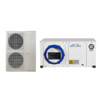
Optional box for placing the unit outside the room, connecting suction hoses.
Optional carbon filters for air purification, refer to maintenance section.
Optional siphon for use when there is excessive underpressure in the intake system.
Details on activating and using the PRO4's day mode dehumidification feature.
| Brand | OPTICLIMATE |
|---|---|
| Model | PRO3 Series |
| Category | Air Conditioner |
| Language | English |