Do you have a question about the OPTICLIMATE SPLIT PRO3 Series and is the answer not in the manual?
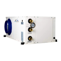
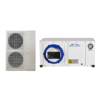
Lists the physical dimensions for various OptiClimate Pro3 Split outdoor units.
Instructions on orienting the fan outlet based on unit placement in narrow spaces.
Explains the alarm output on the PCB for fault detection and connection to alarm systems.
Details the connection and automatic day/night switching based on the built-in light sensor.
Explains the connection and placement of the room temperature sensor for accurate readings.
Guidance on where to hang the remote control for optimal operation.
Details the wiring and connection of the 5-core cable to the outdoor and indoor units.
Provides model-specific requirements for circuit breakers and cable sizes for safe power connection.
Explains how to connect specific timers (LeGrand, Grasslin) to interrupt the heat source for protection.
Advises on placing the outdoor unit in a cool, shaded area with adequate space for air circulation.
Details the connection of the two coolant hoses to the indoor and outdoor units, including precautions.
Explains how to connect the condensation drain to a hose and ensure proper drainage for dehumidification.
Explains the buttons and functions of the remote control for unit operation.
Details the function of the On/Off button and its LED indicators for unit status and faults.
Explains how to switch between day (cooling) and night (heating/dehumidification) modes using the M button.
Guides on using the Fn button to select and adjust fan speeds, including automatic mode.
Guides on setting unit temperature and current time using the remote.
Explains the automatic day/night switching based on the light sensor and manual override.
Provides detailed steps for setting up daily Day/Night programs using the timer function.
Explains setting the humidistat for desired humidity during nighttime dehumidification.
How to read and cycle through various temperature sensors connected to the unit.
Explains how to view active and historical error codes and clear the log.
Explains the display symbol indicating when the compressor is running based on conditions.
Explains the display symbol for active heaters and their operating conditions.
Explains the display symbol indicating when the outdoor unit's fan is operational.
Allows enabling/disabling individual or all heating elements for optimal heating control.
Enables adjustment of the temperature threshold for heat source shutdown to prevent overheating.
Configures whether the unit automatically restarts or remains off after a power interruption.
Configures comfort features like night cooling, pre-heating, and gradual cool-down.
Enables dual room cooling capability, requiring additional components for operation.
Allows setting the alarm output to Normally Open (N.Ö.) or Normally Closed (N.C.).
Configures the timer output for high temperature alarms and synchronization with the clock.
Adjusts the temperature difference for compressor cycling to prevent rapid on/off switching.
Sets the minimum and maximum adjustable temperatures for the pre-heating function.
Sets the minimum and maximum adjustable temperatures for the cooling function.
Configures the temperature threshold for activating the anti-freeze alarm for the cooling block.
Sets the temperature threshold and time for the heatsink overheat alarm.
Calibrates various temperature sensors for accurate readings in different zones.
Adjusts the rest period between compressor cycles to optimize operation.
Configures outdoor fan activation temperature and operational delay.
Configures the temperature threshold for the high outdoor air temperature alarm.
Allows enabling or disabling the display lighting on the remote control.
Outlines regular checks, cleaning, and filter replacement for optimal unit operation.
Guides on diagnosing and resolving problems when the unit fails to turn on.
Addresses issues related to incorrect phase connections, indicated by specific error codes.
Explains potential reasons for circuit breaker trips, such as incorrect installation or settings.
Helps diagnose unit noises and constant cooling by checking outdoor temperature and air intake.
Guides on resolving water leaks from the unit by checking the condensation drain slope and hose.
Lists the seven temperature sensors and their typical operating value ranges.
Details Error 01 related to crossed phases or voltage issues, common in 15000 series.
Explains Error 02 concerning condensate drainage blockages or insufficient slope.
Describes Error 04 indicating the ambient temperature is too low for operation (<4°C).
Covers issues with ambient, heatsink, liquid/return, and dual-room sensors.
Addresses compressor protection, anti-freeze, cooling, and pressure issues.
Optional vibration dampers for reducing noise and ensuring stability, offering superior isolation.
Anti-vibration plates that can be attached to unit panels to minimize radiated noise.
A pump used for condensate removal when drainage is not accessible or is at a lower level.
A valve with a servo motor for enabling dual-room cooling functionality.
A box for connecting hoses to suck warm air from the room for the outdoor unit.
Refers to carbon filters for maintenance, linking to the Inspection and Maintenance section.
| Type | Split Air Conditioner |
|---|---|
| Refrigerant | R32 |
| Coefficient of Performance (COP) | 3.8 |
| Operating Temperature (Heating) | -7-24°C |
| Power Supply | 220-240V, 50Hz |
| Noise Level (Outdoor Unit) | 50 dB |