Do you have a question about the OPTICLIMATE 6000 PRO3 and is the answer not in the manual?
Explains how to connect the electric solenoid valve with the supplied cable.
Details the connection and function of the water leakage sensor.
Lists specifications for power supply, circuit breakers, and cable thickness.
Illustrates connections for 230V/400V 3-phase and 1-phase power.
Details connections and bridging for 1-phase inverter models.
Details connections and bridging for 3-phase inverter models.
Explains connecting a timer to the unit for high temperature safeguard.
Details water inlet/outlet, solenoid valve installation, and pipe insulation.
Describes filter placement and water supply line insulation.
Configures anti-freeze and cooling block overheat protection and duration.
Discusses common issues like no power, phase problems, and noises.
Lists and explains initial error codes related to drains, temperature, and sensors.
Lists and explains further error codes for leaks, safeguards, pressure, and sensors.
Provides a concise list of error codes from E:01 to E:19 for quick reference.
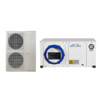
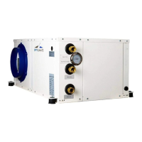
The OptiClimate Pro 3 and Pro 4 (Inverter) are optimal climate control units designed for managing temperature and humidity in various environments. This device is primarily a cooling unit but also offers heating and dehumidification functionalities, making it versatile for maintaining specific climate conditions.
The OptiClimate units are designed to provide precise climate control. They operate by adjusting cooling capacity based on demand. Unlike non-inverter models that operate on an on/off basis, the inverter models modulate the compressor speed (harder/softer) to meet the required cooling capacity. This results in a more stable climate and prevents frequent tripping due to overcapacity. The inverter function is linked to the fan speed; when fans are set to automatic in day mode, the inverter function is active. If fans are set at a fixed rate, the inverter function is switched off, and the compressor runs at a fixed rate.
The unit offers both day and night modes, which can be configured for cooling, heating, and dehumidifying. In day mode, the primary function is cooling, while in night mode, it switches to heating and dehumidifying. An automatic light cell sensor can detect light conditions to automatically switch between day and night modes. Alternatively, a timer function allows for scheduled day/night transitions.
Dehumidification is a key feature. During cooling, the unit automatically dehumidifies the air. For the Pro4 model, super dehumidification can be activated in day mode even without a cooling demand, and in this specific scenario, no water is consumed. In night mode, dehumidification is controlled by an automatic moisture meter. The unit also includes electrical heating elements that activate during night mode if the temperature drops below a preset value.
Safety features are integrated throughout the system. A high-temperature safeguard can switch off external heat sources (e.g., lamps) if the room temperature becomes too high. An anti-freeze protection system monitors the cooling block and water temperatures to prevent freezing. Water leakage sensors detect leaks and automatically close the solenoid valve to stop water supply. An alarm port provides contact for external alarm systems (like GSM detectors) in case of malfunctions or errors.
The OptiClimate units are available in various models (2000 PRO3 & PRO4, 3500 PRO3 & PRO4, 6000 PRO3 & PRO4, 10000 PRO3 & PRO4, 15000 PRO3 & PRO4) with options for 1-phase (230V) or 3-phase (230V or 400V) electrical connections. Each model has specific recommendations for circuit breaker (MCB) and cable thickness to ensure safe operation. For instance, a 2000 PRO3 & PRO4 1-phase unit requires a D16 2.5mm² cable, while a 15000 PRO3 & PRO4 3-phase unit might require a D35 4.0mm² cable.
The cooling capacity is factory-set at 1.6 MPa, with an average range of 1.5-1.7 MPa. This can be adjusted by turning a set screw on the capacity control, allowing for higher (down to 1.3 MPa) or lower (up to 2.0 MPa) cooling capacity depending on the application. Higher cooling capacity consumes more water.
The unit uses water for cooling, and all types of cooling water (tap, well, pond, or swimming pool water) can be used, though tap water is preferred to avoid reliance on additional electric pumps and potential issues with clay and iron particles accumulating in the heat exchanger. Copper pipes of 15mm or LDPE pipes of 16mm are sufficient for most units, with larger main pipes (20mm copper or 20-25mm LDPE) recommended for installations exceeding 15 kW cooling capacity.
Installation requires specific clearances: at least 15cm of space between the wall and the backside (where filters and air inlet are located), and 15cm between the topside and the ceiling to ensure proper air suction and prevent contact noises. The unit should be mounted with a slight slope (at least 1cm lower on the condensation drain side) to ensure proper condensate drainage. Rubber shock absorbers are provided for suspended installation or solid base placement to minimize noise. Special insulating springs are available for extra quiet environments.
Electrical connections involve removing a panel to access terminals for the magnetic valve, water leakage sensor, automatic moisture meter, remote control, and room temperature sensor. Cables for these components are led through an opening at the bottom of the panel, and the power cable through a black feed-through rubber at the side. The solenoid valve connects to terminals N and 7, with an option for earthing. The water leakage sensor connects to the eighth terminal on the printed circuit board and should be placed on the ground at the lowest point.
The remote control allows users to set temperature, time, fan speed, and switch between day/night modes. It also provides access to sensor readings (C:01 to C:07 for cooling block, drain water, supplied water, intake air, outlet air, low-pressure refrigerant, and water leakage temperatures) and error codes (E:XX). The fan speed can be set to automatic, low, medium, or high.
The Settings menu (accessed by holding the 'S' key for >6 seconds) allows for customization of various parameters (D:01 to D:32). These include switching heating elements on/off (D:01), adjusting temperature safeguard limits (D:02), enabling/disabling auto-restart after power interruption (D:03), activating night cooling (D:04), pre-heating (D:05), slow cool-down (D:06), dual room cooling (D:07), alarm port configuration (D:08), water valve options (D:09), timer port settings (D:10), and hysteresis of temperature control (D:11). Users can also adjust minimum/maximum heating and cooling temperatures (D:12 to D:15), anti-freeze protection temperatures (D:16, D:17), cooling water temperature alarms (D:18, D:19), cooling block too hot alarms (D:21, D:22), and temperature compensation for various sensors (D:23 to D:26). Further settings include compressor resting time (D:27), water leakage alarm on/off (D:28), display lighting (D:29), beep on/off (D:30), Fahrenheit/Celsius display (D:31), and super dehumidification for Pro4 (D:32).
Regular inspection and maintenance are crucial for optimal performance. All water connection couplings should be frequently checked for proper tightening and leaks. The black magnetic coil of the solenoid valve should be inspected for thickening, which could indicate poor contact and lead to coil burnout.
The dust filter at the backside of the unit needs to be checked every 10-12 weeks for dust accumulation and cleaned with a vacuum cleaner. The carbon filter, which is essential for proper operation, should be replaced every 10-12 weeks. To replace it, the dust filter must first be removed.
If a humidifier is used, it must be connected to a reverse osmosis filter or scale filter to prevent fan faults caused by lime deposits, which are not covered under warranty. If the dust filter remains clogged with white particles even with a scale filter, an osmosis filter is required, indicating excessively hard water.
The manual also provides a comprehensive fault analysis and error message list (E:01 to E:19) to help users diagnose and resolve issues. For example, E:01 indicates a phase monitor error (for 15000 pro3), E:02 points to a condensation drain problem, and E:08 signifies an active water leakage safeguard. The error log on the remote control displays current and past errors, which can be deleted by pressing and holding the 'R' key once resolved.
| Refrigerant | R410A |
|---|---|
| Weight (Indoor Unit) | 15 kg |
| Type | Air Conditioner |
| Cooling Capacity | 6000 W |
| Heating Capacity | 6000 W |