6
Electrical Connections
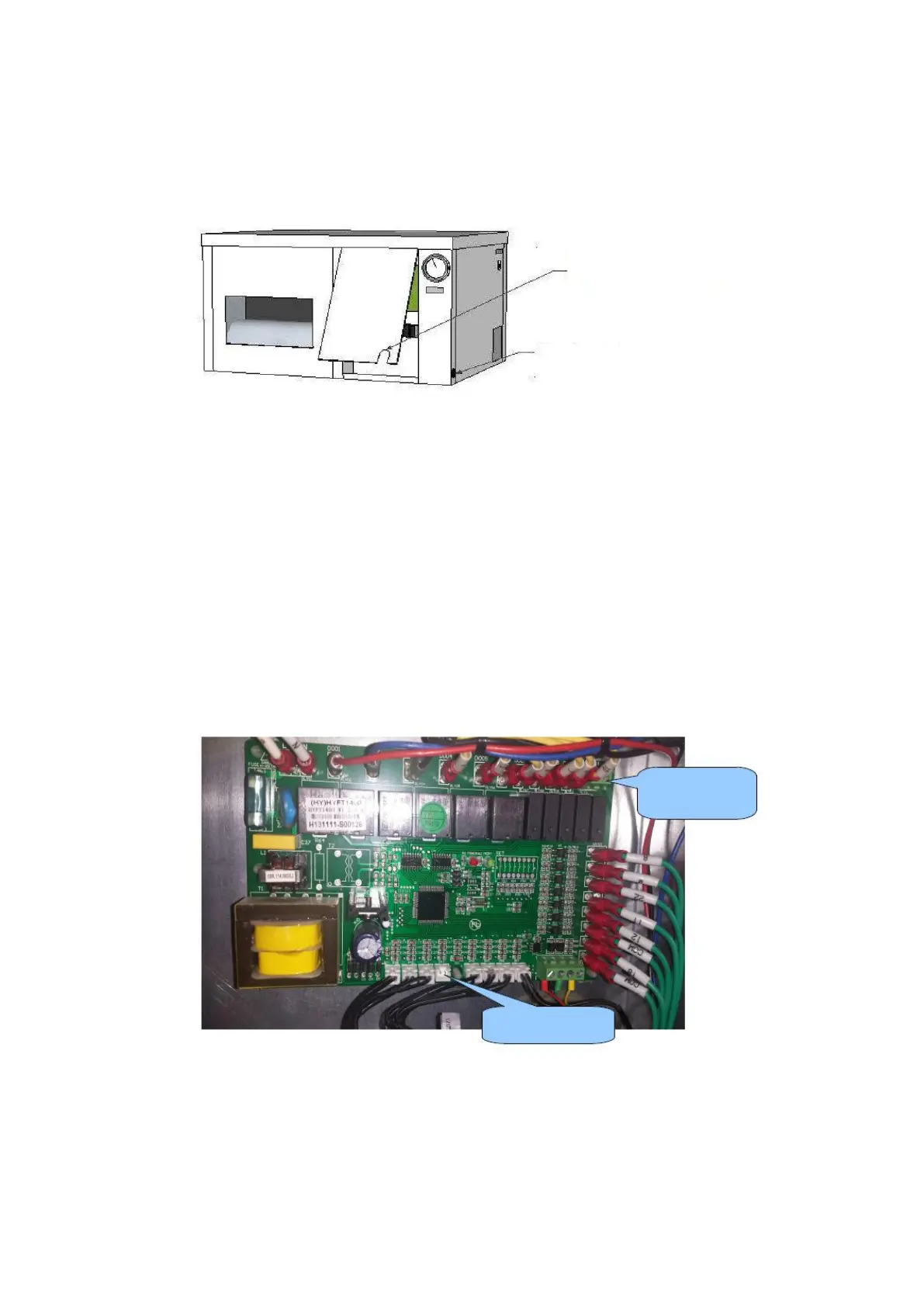
In order to make the various electrical connections they have to be to the left of the panel, the first
manometer dismantled.
Included is a 5-core cable, humidistat, remote and room temperature. The wiring of this can be fed
through the opening at the bottom of the panel. The power cable for the power supply to the side is
led by the black rubber grommet.
Alarm Output
On the PCB is an alarm output, it is activated (contacts) when a fault (error) is detected. This output
can be used with a mobile phone detector or connected to an alarm system. The output can be set
to NO or NC via the Settings menu. This means that the contact is opened or closed by a
notification. See the manual of the mobile phone detector or alarm.
Humidistat with light cell
The humidistat supplied with built-in light sensor is already connected. The cable must to be guided
through the opening in the panel only, The unit should be suspended in space and The light cell in
the humidistat
must not be covered. OptiClimate automatically switches from day to night mode.
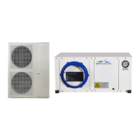
Humidistat, Remote terminal,
Outdoor unit, Temperature sensors