Assembly and maintenance instruction recirculating ball
OPTIMUM
MASCHINEN - GERMANY
5. Dezember 2007Page 8 Recirculating ball screw assembly and maintenance instruction ; Version 2.0
© 2007
GB
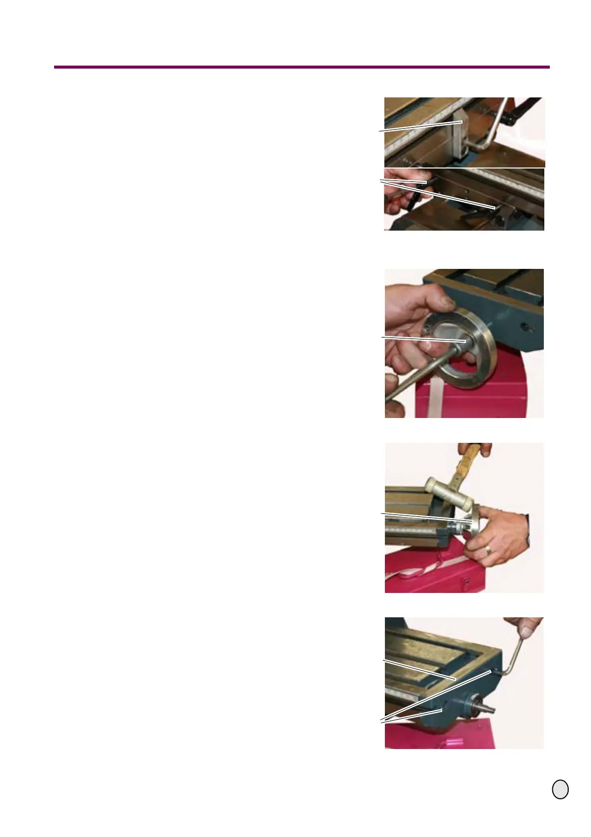
£ Unscrew the indicator and the two
clamping levers of the X-axis.
Fig.1-10: Unscrew indicator and clamping
lever
£ Now disassemble the right side of
the X-axis.
£ Unscrew the hexagon nut from the
spindle.
Fig.1-11: Handwheel right
£ Remove the handwheel, if neces-
sary strike with a plastic tip hammer.
Fig.1-12: Handwheel right
£ Disassemble the two screws on the
right side of the X-axis.
Fig.1-13: Disassemble screws
Indicator
Clamping lever
Unscrew the
hexagon nut from
the X-axis
Disassemble hand-
wheel of the X-axis
Covering plate
Screws
 Loading...