Do you have a question about the Optimum OP-DFST and is the answer not in the manual?
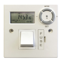
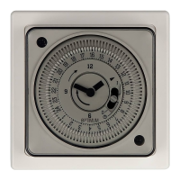
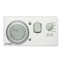
The Optimum Digital Fused Spur Timer, model OP-DFST, is a sophisticated electrical control device designed to manage the power supply to an appliance or circuit with precision. It functions as a digital timer, allowing users to program specific ON/OFF times for connected loads, thereby automating their operation. The device is equipped with a clear digital display that shows the current time and program status, along with intuitive buttons for setup and control. A key safety feature is the integrated fuse, providing essential circuit protection for the connected load.
The primary function of the OP-DFST is to provide timed control over an electrical circuit. It allows users to set up to 24 individual ON/OFF programs, enabling precise scheduling of when power is supplied to a connected appliance. This makes it ideal for managing devices that need to operate at specific times, such as water heaters, towel rails, or other fixed appliances. The timer operates on a 220-240V AC 50Hz supply and is designed for permanent installation as a fused spur.
The device features a real-time clock that can be set to the current hour, minute, and day. This clock forms the basis for all programmed operations. Users can define specific ON and OFF times for each of the 24 available programs. These programs can be set for individual days of the week or for various combinations of days, offering significant flexibility in scheduling. For example, a program can be set to run every weekday, only on weekends, or on specific non-consecutive days like Monday, Wednesday, and Friday.
In addition to programmed operation, the OP-DFST offers manual override options. This allows users to temporarily or permanently switch the connected load ON or OFF, irrespective of the programmed schedule. The manual override modes include "ALWAYS ON" (timer is permanently ON), "PROG ON" (timer is in program mode ON), "PROG OFF" (timer is in program mode OFF), and "ALWAYS OFF" (timer is permanently OFF). This flexibility ensures that users can adapt the device's operation to immediate needs without having to reprogram the entire schedule.
The integrated BS1362 13 Amp cartridge fuse provides crucial overcurrent protection for the connected radial or spur connection. This ensures the safety of the appliance and the electrical circuit by preventing damage from excessive current flow. The device also features a double pole isolation switch, enhancing safety during maintenance or when the connected appliance needs to be completely de-energized.
Setting up and using the OP-DFST involves a series of straightforward steps, guided by the device's buttons and digital display.
To begin, the timer's internal clock needs to be set to the correct current time and day.
The OP-DFST supports up to 24 ON/OFF programs.
Users can review all programmed settings.
The manual override feature allows for immediate control over the connected load.
Individual programs can be deleted if no longer needed.
The OP-DFST is designed for minimal user maintenance after installation.
Installation of the OP-DFST must be carried out by a qualified person in accordance with current IEE wiring regulations. Safety precautions are paramount:
By following these instructions, users can effectively utilize the Optimum Digital Fused Spur Timer to automate and manage their electrical appliances safely and efficiently.
| Type | Digital Timer |
|---|---|
| Mounting Type | DIN Rail |
| Current Rating | 5A |
| Contact Configuration | SPDT |
| Operating Modes | On-Delay, Off-Delay, Interval |
| Timer Settings | 0.1s to 9999h |
| Mounting | DIN Rail |
| Number of Channels | Single Channel |