7. Specification
Supply: 220-240V AC 50Hz
Temperature rating T45 Fuse:
BS1362, 13A Isolation: double
pole switch
Switch type: mains, normally open
Rating:
13A resistive / 8A inductive
Not suitable for direct switching of lighting
types: HID, SON, LED—use a contactor
Class II control / Protection class IP20
Complies with European Norm
EN 60730-1: 2011Automatic Electrical Con-
trols for Household and similar use,
and European Directives:
LVD; EMC; RoHS
www.tfc-group.co.uk
TFC Group LLP Tonbridge TN9 1TB
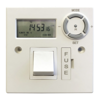
Digital fused spur timer
OP-DFST
User instructions
1. Set the timer
2. Setting a program
3. Check program settings
4. Manual override
5. Installation instructions
6. Wiring diagram
7. Specification
5. Installation instructions.
Please read these instructions fully before commenc-
ing work. The OP-DFST must be installed by a qual-
ified person, in accordance with best practise and
current IEE wiring regulations. Do not install the
timer onto a flammable surface, or keep stored mate-
rials too close. The installed timer should have clear-
ance of at least 150mm in all directions.
Ensure the supply is switched off. In addition, re- move
any fuse protection or turn off the circuit break- er. The
OP-DFST is designed to be installed onto a flush or
surface-mounted electrical back-box of mini- mum
16mm depth. A BS1362 13 Amp cartridge fuse is
pre-installed as circuit protection for the radial, or spur
connection.
Make sure that the total load on the circuit - with the
additional < 13A load connected to the fused spur
timer - does not exceed the capacity of the circuit
cable, fuse or circuit breaker.
Installation:
Connect the incoming supply, and the outgoing load
with the wiring diagram (Figure 1.). Use the earth
continuity terminal which will be provided in a metal
patress box, or the supplied screw terminal connect-
or if using a moulded surface mounted box. Bare earth
conductors must be sleeved. A flexible cable outlet,
with cable restraint is provided. If the flexible cable
outlet is required, remove the blanking cover and route
the flexible load cable via the cable re- straint and the
outlet hole. Check that all conductors are correctly
connected, and terminals are fully tight- ened.
Secure the connected timer to the back-box with the
25mm machine screws provided. Make sure that
cables are carefully routed and stowed to avoid
pinching, stress or damage.
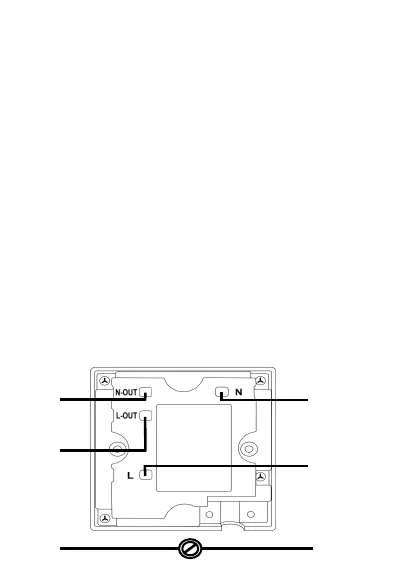
6. Wiring diagram:
N
Mains
supply
L
N
Load
L
E
E
Figure 1.
F
U
S
E
+
R
-
S E T
M O D E
 Loading...