EasyManua.ls Logo

Optimum Optiturn TU 2506 User Manual

Optimum Optiturn TU 2506
202 pages
Go to English
To Next Page IconTo Next Page
Page #1 background imageLoading...
Page #1 background image
D
OPTIMUM
MASCHINEN - GERMANY
Drehmaschine
Lathe
Betriebsanleitung - DE
Operating manual - GB

Table of Contents

Question and Answer IconNeed help?

Do you have a question about the Optimum Optiturn TU 2506 and is the answer not in the manual?

Optimum Optiturn TU 2506 Specifications

General IconGeneral
BrandOptimum
ModelOptiturn TU 2506
CategoryLathe
LanguageEnglish

Summary

Preface

1 Safety

Glossary of symbols

Explains the meaning and use of warning notices.

Information

Contact information for the manufacturer.

1.1 Safety instructions (warning notes)

1.1.1 Classification of hazards

Overview of safety warning symbols and warning signs.

1.2 Intended use

1.3 Reasonably foreseeable misuses

1.3.1 Avoiding misuses

Methods to prevent misuse of the lathe.

1.4 Possible dangers caused by the machine

1.5 Qualification of personnel

1.5.1 Target group

Identifies who the manual is addressed to.

1.5.2 Authorized personnel

Specifies who is permitted to operate the machine.

1.5.3 Obligations of the operating company

Outlines the company's responsibilities for staff training.

1.5.4 Obligations of the operator

Details the operator's responsibilities.

1.5.5 Additional requirements regarding the qualification

Specifies extra requirements for electrical work.

1.6 Operators positions

1.7 Safety measures during operation

1.8 Safety devices

1.9 EMERGENCY-STOP button

1.9.1 Lockable main switch (only TU 2506V, TU2807V)

Describes the lockable main switch function.

1.9.2 Protective cover with safety switch

Explains the protective cover and its safety switch.

1.9.3 Lathe chuck protection with position switch

1.9.4 Lathe chuck key

1.10 Safety check

1.11 Personnel protective equipment

1.12 For your own safety during operation

1.13 Disconnecting and securing the lathe

1.14 Using lifting equipment

1.15 Mechanical maintenance work

2 Technical data

2.1 Electrical connection

Details electrical connection specifications for models.

2.2 Machine data

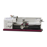
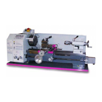
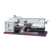
Lists technical specifications of the machine.

2.3 Working area

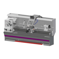
Provides dimensions of the machine's working area.

2.4 Environmental conditions

2.5 Operating material

2.6 Emissions

2.7 Dimensions, installation plan TU2506

2.8 Dimensions, installation plan TU2506V

2.9 Dimensions, installation plan TU2807

2.10 Dimensions, installation plan TU2807V

2.11 Distance between centres, height of centres TU2506, TU2506V

2.12 Distance between centres, height of centres TU2807, TU2807V

3 Assembly

3.1 Scope of delivery

Information on checking the delivered machine parts.

3.2 Transport

Guidelines for safe transport and handling of the machine.

3.3 Storage

3.4 Installation and assembly

3.4.1 Requirements regarding the installation site

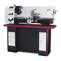
Criteria for selecting a suitable installation location.

3.4.2 Load suspension point

3.4.3 Installation

3.5 Assembly of the synchronous belt and V-belt on the lathe

3.5.1 Assembly of the synchronous belt on the lathe TU 2506, TU 2807, TU2807 V

Steps for assembling synchronous belt on specific models.

3.5.2 Assembly of the synchronous belt on the lathe TU 2506 V

Steps for assembling synchronous belt on TU 2506 V.

3.5.3 Assembly of the V-belt on the lathe

Procedure for installing and tensioning the V-belt.

3.6 First commissioning

3.6.1 Warming up the machine

Procedure for warming up the machine before operation.

3.6.2 Cleaning and lubricating

Instructions for cleaning and lubricating machine parts.

3.6.3 Visual inspection

What to check during a visual inspection.

3.6.4 Functional test

Steps for performing functional tests.

3.6.5 Electrical connection

Guidance on connecting the electrical supply.

3.6.6 Functional check

3.7 Available accessories

3.8 Mounting instruction

3.8.1 Mounting instruction chuck flange

Detailed steps for mounting the chuck flange.

3.8.2 Chuck flange

3.8.3 Mounting instruction of collet chuck holder

3.8.4 Mounting of follow rest TU 2506 (V)

3.8.5 Mounting of follow rest TU 2807 (V)

3.8.6 Mounting of steady rest TU 2506 (V)

3.8.7 Mounting of steady rest TU 2807 (V)

3.9 Safety

3.10 Operating elements for feed

3.11 Tool holder

3.12 Lathe chuck

3.12.1 Replacing the clamping jaws on the lathe chuck

3.13 Speed adjustment

3.13.1 Changing the speed range

Steps to change the speed range of the lathe.

3.13.2 Speed table TU2506

3.13.3 Speed table TU2506V

3.13.4 Speed table TU2807

3.13.5 Speed table TU2807V

3.14 Feed adjustment

3.14.1 Selector switch

How to use selector switches for feed direction and speed.

3.14.2 Changing the change gears

3.14.3 Arrangement of change gears

3.14.4 Tables for thread-cutting

3.14.5 Transmission ratio

3.14.6 Example - assembly of gear wheels for thread 0.75mm 1.5mm 3mm

3.15 Feed engaging lever

3.16 Fixing the lathe saddle

3.17 Turning tapers

3.17.1 Turning short tapers with the top slide

How to turn short tapers using the top slide.

3.17.2 Turning tapers with the tailstock

Method for turning tapers using the tailstock.

3.17.3 Turning of cones with high precision

Techniques for precise cone turning.

4. By offsetting the tailstock

Method for turning tapers by offsetting the tailstock.

3.18 Tailstock sleeve

3.19 Clamping a workpiece into the three jaw chuck

3.20 Standard values for cutting data when turning

3.21 Cutting speed table

3.22 Terms for the rotating tool

3.22.1 Cutting edge geometry for turning tools

3.22.2 Types of cutting form levels

Polished section for recessing and cutting off

Polished section for threading

3.23 Tapping of external and internal threads

3.24 Thread types

ISO-trapezoid thread

Round thread

NPT

3.24.1 Metric threads (60° flank angle)

Metric fine-pitch thread

3.24.2 British thread (55° flank angle)

3.24.3 Indexable inserts

Determining the machining method of right-handed and left-handed threads

3.24.4 Examples for thread cutting

Starting the threading

3.25 General working advice - coolant

3.26 Operation TU2506V

3.26.1 Control and indicating elements

Identifies and describes the machine's controls and indicators.

3.26.2 Switching elements

3.26.3 Switching on the machine

3.26.4 Switching off the machine

3.27 Operation TU2807V

3.27.1 Control and indicating elements

Identifies and describes the machine's controls and indicators.

3.27.2 Switching elements

3.27.3 Switching on the machine

3.27.4 Switching off the machine

4 Maintenance

4.1 Safety

Safety precautions for maintenance and repair work.

4.1.1 Preparation

Steps to take before starting maintenance.

4.1.2 Restarting

4.2 Inspection and maintenance

4.3 Repairs

5 Malfunctions

6 Appendix

6.1 Copyright

Legal notice regarding document copyright.

6.2 Terminology/Glossary

Definitions of technical terms used in the manual.

6.3 Change information operating manual

Records of manual revisions and updates.

6.4 Liability claims for defects / warranty

6.5 Note regarding disposal / options to reuse

6.5.1 Decommissioning

6.5.2 Disposal of the packaging of new devices

6.5.3 Disposing of the old device

6.5.4 Disposal of electrical and electronic components

6.5.5 Disposal of lubricants and coolants

6.6 Disposal via municipal collection

6.7 RoHS, 2002/95/EC

6.8 Product follow-up

7 Ersatzteile - Spare parts TU2506 | TU2506V

7.1 Oberschlitten - Top slide

Diagram and details for the top slide spare parts.

7.2 Planschlitten- Cross slide

7.3 Bettschlitten - Bed slide

7.4 Ersatzteilzeichnung Reitstock - Tailstock

7.5 Maschinenbett - Machine bed

7.6 Vorschubgetriebe 1 von 2 - Feed gear 1 of 2

7.7 Vorschubgetriebe 2 von 2 - Feed gear 2 of 2

7.8 Spindelstock 1 von 2 - Headstock 1 of 2

7.9 Spindelstock 2 von 2 - Headstock 2 of 2

7.10 Spindelstock - Headstock TU 2506 V

7.11 Wechselradgetriebe - Change gear

7.12 Ersatzteilliste - Spare parts list TU2506

Pos. 1-71

List of spare parts with item numbers for TU2506.

8 Ersatzteile - Spare parts TU2807 | TU2807V

8.1 Oberschlitten - Top slide

Diagram and details for the top slide spare parts.

8.2 Planschlitten- Cross slide

8.3 Bettschlitten - Bed slide

8.4 Reitstock 2 - Tailstock 2

8.5 Maschinenbett - Machine bed

8.6 Vorschubgetriebe 1 von 2 - Feed gear 1 of 2

8.7 Vorschubgetriebe 2 von 2 - Feed gear 2 of 2

8.8 Spindelstock 1 von 2 - Headstock 1 of 2

8.9 Spindelstock 2 von 2 - Headstock 2 of 2

8.10 Spindelstock - Headstock TU 2807 V

8.11 Wechselradgetriebe - Change gear

8.12 Ersatzteilliste - Spare parts list TU 2807

Pos. 1-66

List of spare parts with item numbers for TU 2807.

9 Schaltpläne - Wiring diagrams

9.1 Schaltplan - Wiring diagram TU 2506 - 230V

Wiring diagram for TU 2506 model at 230V.

9.2 Schaltplan - Wiring diagram TU 2506 / TU 2807 - 400V

Wiring diagram for TU 2506/TU 2807 models at 400V.

9.3 Schaltplan - Wiring diagram TU 2506 V / TU 2807 V

Wiring diagram for TU 2506 V/TU 2807 V models.

Index

Index Entries

Alphabetical listing of topics covered in the manual.

EG - Konformitätserklärung

EC - declaration of conformity

Related product manuals