Do you have a question about the Optoma EP782 and is the answer not in the manual?
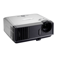
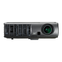
Details specifications and key features of the projector models.
Lists supported resolutions and sync frequencies for computer inputs.
Lists tools and components required for disassembly.
Step-by-step guide to remove the projector's lamp cover.
Procedure to safely detach and remove the projector lamp module.
Instructions for removing the top panel of the projector.
Steps to detach the front ring assembly from the projector.
Guide to removing the projector's keypad assembly.
Procedure for detaching the infrared sensor module.
Steps to remove the rear cover of the projector.
Guide to remove top shielding and wireless components.
Procedure to detach the main logic board from the projector.
Steps for removing the projector's network interface module.
Procedure to detach the input/output board from the projector.
Guide to removing the projector's cooling fan assembly.
Steps to detach the Low Voltage Power Supply module.
Procedure to remove the core optical engine assembly.
Steps to detach the color wheel assembly from the projector.
Procedure for removing the DMD board and chip.
Steps to detach lens assembly components like zoom and focus rings.
Procedure to remove the rod assembly from the projector.
Steps to detach the air ducting components.
Guide to removing the projector's blower fan.
Procedure to detach combined rod blower and duct assemblies.
Steps to remove the projector's wind tunnel assembly.
Guide to removing the honeycombed module.
Procedure to detach the lamp driver board.
Steps to remove limit switch assemblies.
Procedure to remove bottom support shielding.
Steps to detach rear and right speaker modules.
Procedure for adjusting the rod assembly for image alignment.
Instructions for resetting/updating the lamp usage hour counter.
Table indicating LED status codes for troubleshooting.
Step-by-step procedures for common troubleshooting symptoms.
List of equipment required for functional testing.
Instructions to enter and exit the projector's service mode.
Procedure to reset projector settings to factory defaults.
Conditions and environment for performing functional tests.
Guidelines for inspecting projector performance after updates/repairs.
Procedures for testing projector functionality via PC connection.
Tests for evaluating video signal quality and output.
Procedures for measuring optical parameters like brightness and contrast.
Steps to test the projector's network connectivity.
Procedures for testing wireless connectivity and functionality.
Miscellaneous functional tests and checks.
Lists software and hardware required for firmware upgrade.
Step-by-step guide to install the DLP Composer Lite software.
Procedure to install necessary USB drivers for firmware flashing.
Detailed steps to upgrade the projector's firmware using DLP Composer.
Explanation of Extended Display Identification Data (EDID) format.
Lists software and hardware for EDID upgrade.
Steps for setting up the fixture and connections for VGA EDID upgrade.
Procedure for inputting EDID data via VGA/DVI.
Procedure for inputting EDID data via HDMI.
Exploded view and parts list for the bottom housing module.
Exploded view and parts list for the LVPS module.
Exploded view and parts list for main and IO boards.
Exploded view and parts list for the engine module.
Exploded view and parts list for the color wheel module.
Exploded view and parts list for the DC components of EP776.
Exploded view and parts list for the bottom housing module.
Exploded view and parts list for the top cover module.
Exploded view and parts list for the engine module.
Exploded view and parts list for the lamp driver module.
Exploded view and parts list for the LVPS module.
Exploded view and parts list for main and IO boards.
Exploded view and parts list for the optical engine module.
Exploded view and parts list for the limit switch module.
Exploded view and parts list for the engine rod base module.
Exploded view and parts list for the color wheel module.
Exploded view and parts list for EMI bottom shielding.
Exploded view and parts list for the right limit switch module.
Exploded view and parts list for the axial fan module.
Exploded view and parts list for the DC components of EP782.
Exploded view and parts list for the package contents.
Defines the format and meaning of projector serial numbers.
Defines the structure and meaning of PCBA codes.
| Resolution | 1024 x 768 |
|---|---|
| Contrast Ratio | 2000:1 |
| Display Technology | DLP |
| Projection Size | 27-300 inches |
| Inputs | VGA, S-Video, Composite |