Do you have a question about the Optoma GT-7000 and is the answer not in the manual?
Important notice regarding manual updates and changes to the product information.
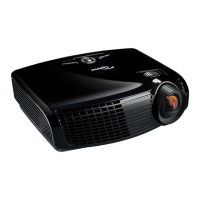
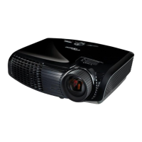
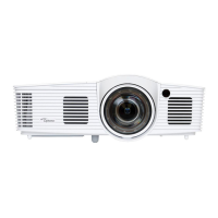
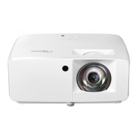
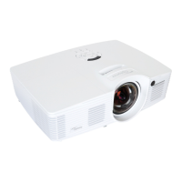
Provides a summary of the projector's key features and technical specifications.
Details the projector's compatibility with various video input modes and resolutions.
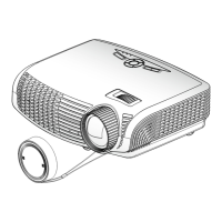
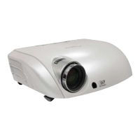
Lists the tools and components required for disassembly and an overview of the product.
Step-by-step instructions for removing the projector's lamp cover.
Procedure for safely removing and handling the projector's lamp module.
Instructions on how to disassemble the top cover assembly of the projector.
Guide to removing the keypad board and individual keypad components.
Steps to detach the infrared sensor from the projector.
Procedure for removing the input/output cover panel.
Instructions for taking off the internal top shielding components.
Detailed steps for removing the main circuit board module from the projector.
Procedure for removing the shielding that protects the main board.
Instructions for removing the shielding around the lamp housing.
Steps to detach the lamp driver module from the projector's chassis.
Procedure for removing the lamp driver assembly.
Procedure for removing the projector's optical engine assembly.
Guide to removing the color wheel and associated photo sensor board.
Instructions for detaching the heat sink assembly.
Procedure for removing the Digital Micromirror Device (DMD) module.
Steps to remove the projector's zoom ring assembly.
Instructions for detaching the projector's focus ring assembly.
Procedure for removing the rod module.
Steps to remove the cooling fan and blower components.
Procedure for detaching the limit switch.
Instructions for removing the thermal switch.
Procedure for detaching the Low Voltage Power Supply (LVPS) module.
Steps to remove the bottom shielding plate.
Instructions for removing the elevator module.
Procedure for adjusting the rod for optimal image quality.
Guide to updating the projector's lamp usage hour counter.
Explains the meaning of different LED status indicators for troubleshooting.
Provides step-by-step procedures for diagnosing and resolving common projector issues.
Lists the necessary tools and equipment for performing function tests and alignment.
Instructions on how to access and operate the projector's service mode.
Procedure to reset the On-Screen Display settings to factory defaults.
Specifies the environmental and operational conditions for testing.
Details the steps for inspecting and verifying projector functions and performance.
Instructions for testing projector performance when connected to a PC.
Procedures for evaluating the quality of video output.
Methods for measuring optical parameters like brightness and contrast.
Covers additional functional checks and inspections not categorized elsewhere.
Lists the software and hardware required for firmware updates.
Step-by-step guide for installing the DLP Composer Lite software.
Instructions for installing the necessary USB drivers for firmware updates.
Detailed steps for performing a firmware update on the projector.
Explanation of Extended Display Identification Data (EDID) and its purpose.
Lists the software and hardware required for EDID upgrades.
Steps for connecting and preparing the system for EDID key-in.
Detailed instructions for inputting and programming EDID data.
Exploded view diagram of the bottom case module for the HD65 projector.
Exploded view diagram of the top case assembly for the HD65 projector.
Exploded view diagram of the optical engine assembly for the HD65 projector.
Exploded view diagram of the rod module for the HD65 projector.
Exploded view diagram of the color wheel assembly for the HD65 projector.
Exploded view diagram of the lamp assembly for the HD65 projector.
Exploded view diagram of the DC assembly for the HD65 projector.
Exploded view diagram of the DP assembly for the HD65 projector.
Explains the format and meaning of the projector's serial number.
Details the serial number format specific to the HD65 model.
Details the serial number format specific to the HD700X model.
Details the serial number format specific to the GT-7000 model.
Defines the structure and components of the PCBA code for projectors.
| Display Technology | DLP |
|---|---|
| Zoom Type | Fixed |
| 3D Ready | Yes |
| Lamp Life (Normal) | 4, 000 hours |
| I/O Ports | HDMI, VGA, Audio in, Audio out, USB |
| Inputs | HDMI, VGA |